


14 - 26
14. OPTIONS AND AUXILIARY EQUIPMENT
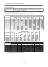
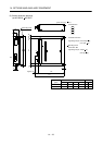
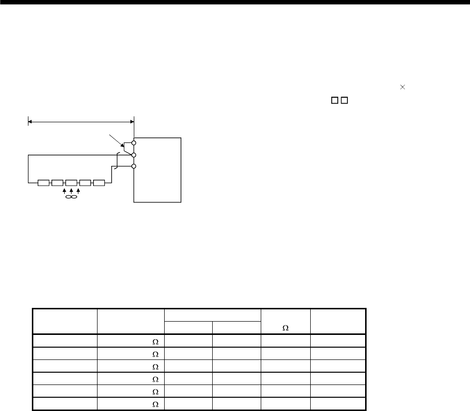
(c) MR-J3-11KT(4) to MR-J3-22KT(4) (when using the supplied regenerative resistor)
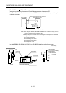
When using the regenerative resistors supplied to the servo amplifier, the specified number of resistors
(4 or 5 resistors) must be connected in series. If they are connected in parallel or in less than the
specified number, the servo amplifier may become faulty and/or the regenerative resistors burn. Install
the resistors at intervals of about 70mm. Cooling the resistors with two cooling fans (92
92, minimum
air flow : 1.0m
3
) improves the regeneration capability. In this case, set " FA" in parameter No.PA02.
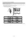
Coolin
g
fan
P
C
Servo amplifie
r
(Note) Series connection
P
1
Do not remove
the short bar.
5m or less
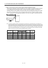
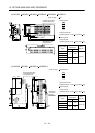
Note. The number of resistors connected in series depends on the resistor type. The thermal sensor is not mounted on the
attached regenerative resistor. An abnormal heating of resistor may be generated at a regenerative circuit failure. Install a
thermal sensor near the resistor and establish a protective circuit to shut off the main circuit power supply when abnormal
heating occurs. The detection level of the thermal sensor varies according to the settings of the resistor. Set the thermal
sensor in the most appropriate position on your design basis or use the thermal sensor built-in regenerative option (MR-
RB5E, 9P, 9F, 6B-4, 60-4 and 6K-4) provided by Mitsubishi Electric Corporation.
Regenerative power [W]
Servo amplifier
Regenerative
resistor
Normal Cooling
Resistance
[
]
Number of
resistors
MR-J3-11KT GRZG400-1.5 500 800 6 4
MR-J3-15KT GRZG400-0.9 850 1300 4.5 5
MR-J3-22KT GRZG400-0.6 850 1300 3 5
MR-J3-11KT4 GRZG400-5.0 500 800 20 4
MR-J3-15KT4 GRZG400-2.5 850 1300 12.5 5
MR-J3-22KT4 GRZG400-2.0 850 1300 10 5