


4 - 24
4. SIGNALS AND WIRING
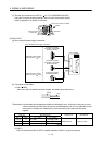
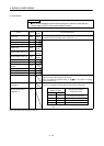
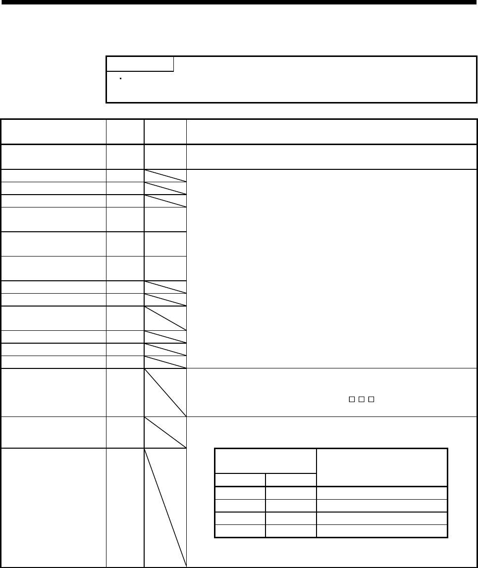
(1) Input device
POINT
Input devices assigned to the CN6 connector pins cannot be used with the
remote input of the CC-Link communication function.
Device Symbol
Connector
pin No.
Functions/Applications
Forced stop EMG CN6-1
Forced stop (EMG) is fixed at CN6-1. Assigning this device to any other pin is
not allowed. For device details, refer to section 3.5.1 (1).
Servo-on SON For device details, refer to section 3.5.1 (1).
Forward rotation start ST1
Reverse rotation start ST2
Proximity dog DOG
CN6-2
(Note)
Forward rotation stroke end LSP
CN6-3
(Note)
Reverse rotation stroke end LSN
CN6-4
(Note)
Automatic/manual selection MD0
Temporary stop/Restart TSTP
Internal torque limit
selection
TL1
Proportion control PC
Gain changing CDP
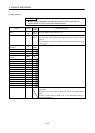
Reset RES
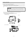
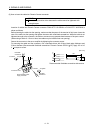
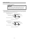
Clear CR
Turn CR on to clear the position control counter droop pulses on its leading
edge. The pulse width should be 10ms or more.
When the parameter No.PD22 setting is "
1", the pulses are always
cleared while CR is on.
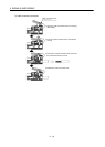
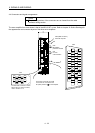
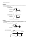
Manual pulse generator
multiplication 1
TP0
Used to select the multiplication factor of the manual pulse generator.
When it is not selected, the parameter No.PA05 setting is made valid.
Manual pulse generator
multiplication 2
TP1
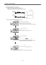
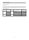
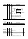
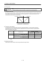
(Note) Input device
TP1 TP0
Manual pulse generator
multiplication factor
0 0 Parameter No.PA05 setting
0 1 1 time
1 0 10 times
1 1 100 times
Note. 0: OFF
1: ON
Note. These are pin Nos. assigned at default.