


3 - 11
3. CC-LINK COMMUNICATION FUNCTIONS
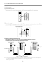
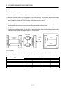
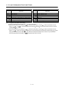
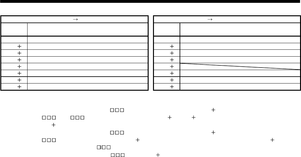
Programmable controller Servo amplifier (RWwn) Servo amplifier Programmable controller (RWrn)
(Note 1)
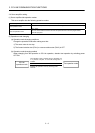
Address No.
Signal name
(Note 1)
Address No.
Signal name
RWwn (Note 2) Monitor 1 RWrn Monitor 1 data lower 16 bit
RWwn 1 (Note 2) Monitor 2 RWwn 1 Monitor 1 data upper 16 bit
RWwn 2 Instruction code RWwn 2 Respond code
RWwn 3 Writing data RWwn 3 Reading data
RWwn 4 (Note 3) Position command data lower 16 bit/Point table No. RWwn 4
RWwn 5 Position command data upper 16 bit RWwn 5 Monitor 2 data lower 16 bit
RWwn 6 (Note 4) Speed command data/Point table No. RWwn 6 Monitor 2 data upper 16 bit
RWwn 7 Reserved RWwn 7 Reserved
Note 1. "n" depends on the station number setting.
2. Specify the code of the lower 16 bit as the monitor code of 32-bit data.
3. When the parameter No.PC30 setting is "
0", specify the point table No. in RWwn 4. When the parameter No.PC30
setting is "
1" or " 2", specify the position data in RWwn 4/RWwn 5 and turn ON Position instruction execution
demand (RY(n
2)0).
4. When the parameter No.PC30 setting is "
1", specify the point table No. in RWwn 6. When the parameter No.PC30
setting is "
2", specify the speed data in RWwn 6, and turn ON Speed instruction execution demand (RY(n 2)1). When
setting the parameter No.PC30 to "
2", always set the acceleration/deceleration time constant in the point table No.1.
When the parameter No.PC30 setting is "
0", the RWwn 6 value is not used.