


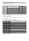
16 - 107
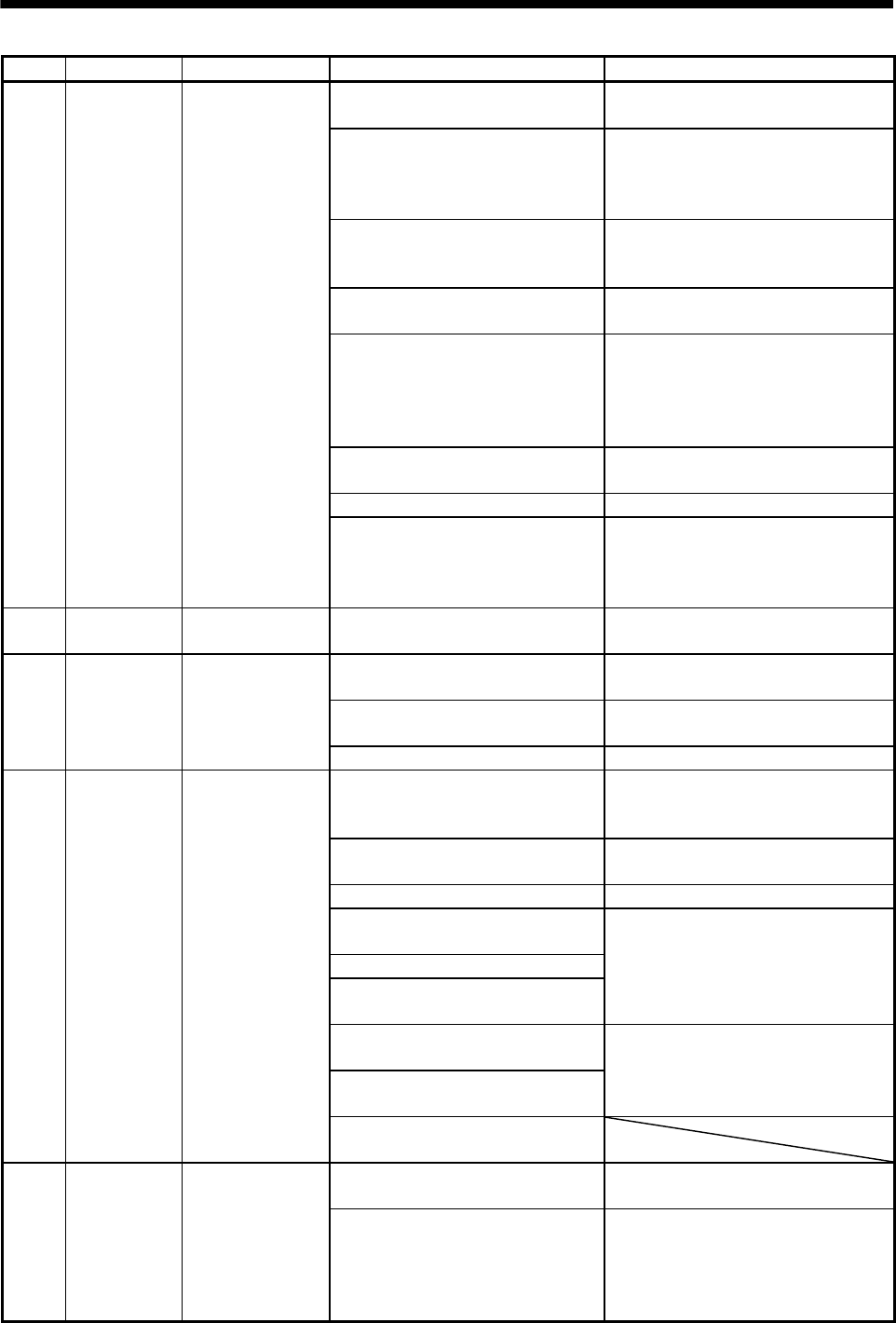
16. INDEXER POSITIONING OPERATION
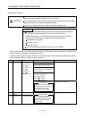
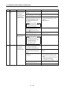
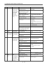
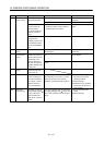
Display Name Definition Cause Action
A52 Error excessive 1. Acceleration/deceleration time
constant is too small.
Increase the acceleration/deceleration
time constant.
2. Forward rotation torque limit
(parameter No.PA11) or reverse
rotation torque limit (parameter
No.PA12) are too small.
Increase the torque limit value.
3. Motor cannot be started due to
torque shortage caused by power
supply voltage drop.
1. Check the power supply capacity.
2. Use servo motor which provides larger
output.
The difference
between the model
position and the
actual servo motor
position exceeds
three rotations.
(Refer to the
function block
diagram in section
1.1.2.)
4. Position loop gain (parameter
No.PB08) value is small.
Increase set value and adjust to ensure
proper operation.
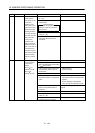
5. Servo motor shaft was rotated by
external force.
1. When torque is limited, increase the
limit value.
2. Reduce load.
3. Use servo motor that provides larger
output.
6. Machine struck something. 1. Check operation pattern.
2. Install limit switches.
7. Encoder faulty. Change the servo motor.
8. Wrong connection of servo motor.
Servo amplifier’s output terminals U,
V, W do not match servo motor’s
input terminals U, V, W.
Connect correctly.
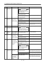
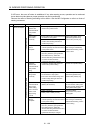
A61 Operation
alarm
Setting mistake of
auxiliary function.
"1" or "3" is set for the auxiliary function
of point table No.255.
Set "0" or "2" for the value of auxiliary
function.
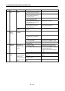
A8A 1. Communication cable breakage. Repair or change the communication
cable.
Serial
communication
time-out error
2. Communication cycle longer than
regulated time.
Shorten the communication cycle.
Communication
stopped for longer
than the specified
time.
3. Wrong protocol. Correct protocol.
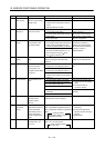
A8D CC-Link alarm 1. The station number switch
(STATION NO.) setting is 0 or not
less than 65.
Set the station number to within the range
1 to 64, and switch power on.
Normal
communication with
the master station
cannot be made.
2. The baud rate switch (MODE) setting
is outside the range 0 to 4.
Set the baud rate switch (MODE) to
within the range 0 to 4.
3. The transmission status is abnormal. Reexamine the wiring.
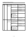
4. CC-Link twisted cable wiring
incorrect.
5. CC-Link twisted cable faulty.
6. The CC-Link connector has come
off.
1. Repair or change the CC-Link twisted
cable.
2. Connect the cable or connector
correctly.
7. The terminating resistor is not
connected.
Connect the terminating resistor correctly.
8. Noise entered the CC-Link twisted
cable.
9. The programmable controller CC-
Link unit was reset.
A8E 1. Communication cable fault
(Open cable or short circuit).
Repair or change the cable.
Serial
communication
error
Serial
communication error
occurred between
servo amplifier and
communication
device (e.g. personal
computer).
2. Communication device (e.g. personal
computer) faulty.
Change the communication device (e.g.
personal computer).