


16 - 12
16. INDEXER POSITIONING OPERATION
Device No.
Signal name
(Device name)
Description
1 station
occupied
2 stations
occupied
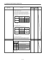
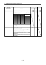
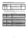
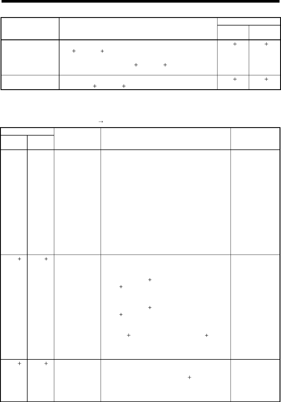
Trouble A trouble is assigned to the CN6-15 pin as an external output signal.
RX(n
1)A or RX(n 3)A turns ON when the protective circuit is activated to
shut off the base circuit.
When no alarm has occurred, RX(n
1)A or RX(n 3)A turns OFF within
about 1.5s after power is switched ON.
RX(n
1)A RX(n 3)A
Remote station
communication ready
This signal turns ON at power-on and turns off at a trouble occurrence or in
the reset (RY(n
1)A or RY(n 3)A) ON status.
RX(n
1)B RX(n 3)B
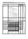
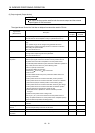
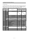
(3) Remote registers
The signal whose Remote Register field has an oblique line cannot be used.
(a) Input (Programmable controller
servo amplifier)
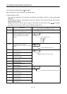
Remote register
1 station
occupied
2 stations
occupied
Signal name Description Setting range
RWwn RWwn Monitor 1 Demands the status indication data of the servo amplifier.
1) When 1 station is occupied
Setting the monitor code of the status indication item to be
monitored to RWwn and turning RYn8 to ON sets data to
RWrn. RXn8 turns on at the same time.
2) When 2 stations are occupied
Setting the monitor code of the status indication item to be
monitored to RWwn and turning RYn8 to ON sets data to
RWrn. RXn8 turns on at the same time.
When demanding 32-bit data, specifying the lower 16-bit
code No. and turning RYn8 to ON sets the lower 16-bit data
to RWwn and the upper 16-bit data to RWrn. data is stored
in the RXn8. RXn8 turns on at the same time.
Refer to section 16.2.3 for the item of the monitor code of
the status indication.
Refer to section
16.2.3.
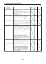
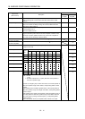
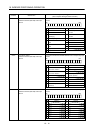
RWwn 1 RWwn 1 Monitor 2 Demands the status indication data of the servo amplifier.
1) When 1 station is occupied
Setting the monitor code of the status indication item to be
monitored to RWwn
1 and turning RYn8 to ON sets data to
RWrn
1. RXn8 turns on at the same time.
2) When 2 stations are occupied
Setting the monitor code of the status indication item to be
monitored to RWwn
1 and turning RYn8 to ON sets data to
RWrn
5. RXn8 turns on at the same time.
When demanding 32-bit data, specifying the lower 16-bit
code No. and turning RYn8 to ON sets the lower 16-bit data
to RWwn
5 and the upper 16-bit data to RWrn 6. Data is
stored in the RXn8. RXn8 turns on at the same time.
Refer to section 16.2.3 for the item of the monitor code of
the status indication.
Refer to section
16.2.3.
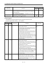
RWwn 2 RWwn 2 Instruction code Sets the instruction code used to perform parameter or point
table data read and write, alarm reference or the like.
Setting the instruction code No. to RWwn
2 and turning
RYn9 to ON executes the instruction. RXn9 turns to ON on
completion of instruction execution.
Refer to section 16.2.4 (1) for instruction code No. definitions.
Refer to section
16.2.4 (1).