


14 - 33
14. OPTIONS AND AUXILIARY EQUIPMENT
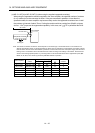
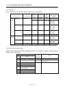
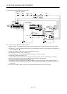
14.3.1 Selection
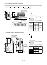
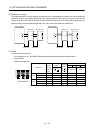
Use a combination of servo amplifier, brake unit and resistor unit listed below.
Brake unit Resistor unit
Number of
connected
units
Permissible
continuous
power [kW]
Total
resistance
[
]
Applicable servo
amplifier
FR-BU2-15K FR-BR-15K 1 0.99 8 MR-J3-500T (Note) 200V
class
2 (parallel) 1.98 4 MR-J3-500T
MR-J3-700T
MR-J3-11KT
MR-J3-15KT
FR-BU2-30K FR-BR-30K 1 1.99 4 MR-J3-500T
MR-J3-700T
MR-J3-11KT
MR-J3-15KT
FR-BU2-55K FR-BR-55K 1 3.91 2 MR-J3-11KT
MR-J3-15KT
MR-J3-22KT
MT-BR5-55K 1 5.5 2 MR-J3-22KT
400V
class
FR-BU2-H30K FR-BR-H30K 1 1.99 16 MR-J3-500T4
MR-J3-700T4
MR-J3-11KT4
FR-BU2-H55K FR-BR-H55K 1 3.91 8 MR-J3-11KT4
MR-J3-15KT4
MR-J3-22KT4
FR-BU2-H75K MT-BR5-H75K 1 7.5 6.5 MR-J3-22KT4
Note. The combination is limited only when using with the servo motors HC-LP302, HC-RP353, HA-LP502 or HC-UP352.
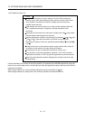
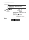
14.3.2 Brake unit parameter setting
Normally, when using the FR-BU2-(H), changing parameters is not necessary. Whether a parameter can be
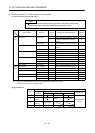
changed or not is listed below.
Parameter
No. Name
Change
possible/
impossible
Remarks
0 Brake mode switchover Impossible Do not change the parameter.
1 Monitor display data selection Possible Refer to the FR-BU2-(H) Brake Unit
Instruction Manual.
2 Input terminal function selection 1
3 Input terminal function selection 2
77 Parameter write selection
78 Cumulative energization time
carrying-over times
CLr Parameter clear
ECL Alarm history clear
C1 For manufacturer setting
Impossible Do not change the parameter.