14 - 25
14. OPTIONS AND AUXILIARY EQUIPMENT
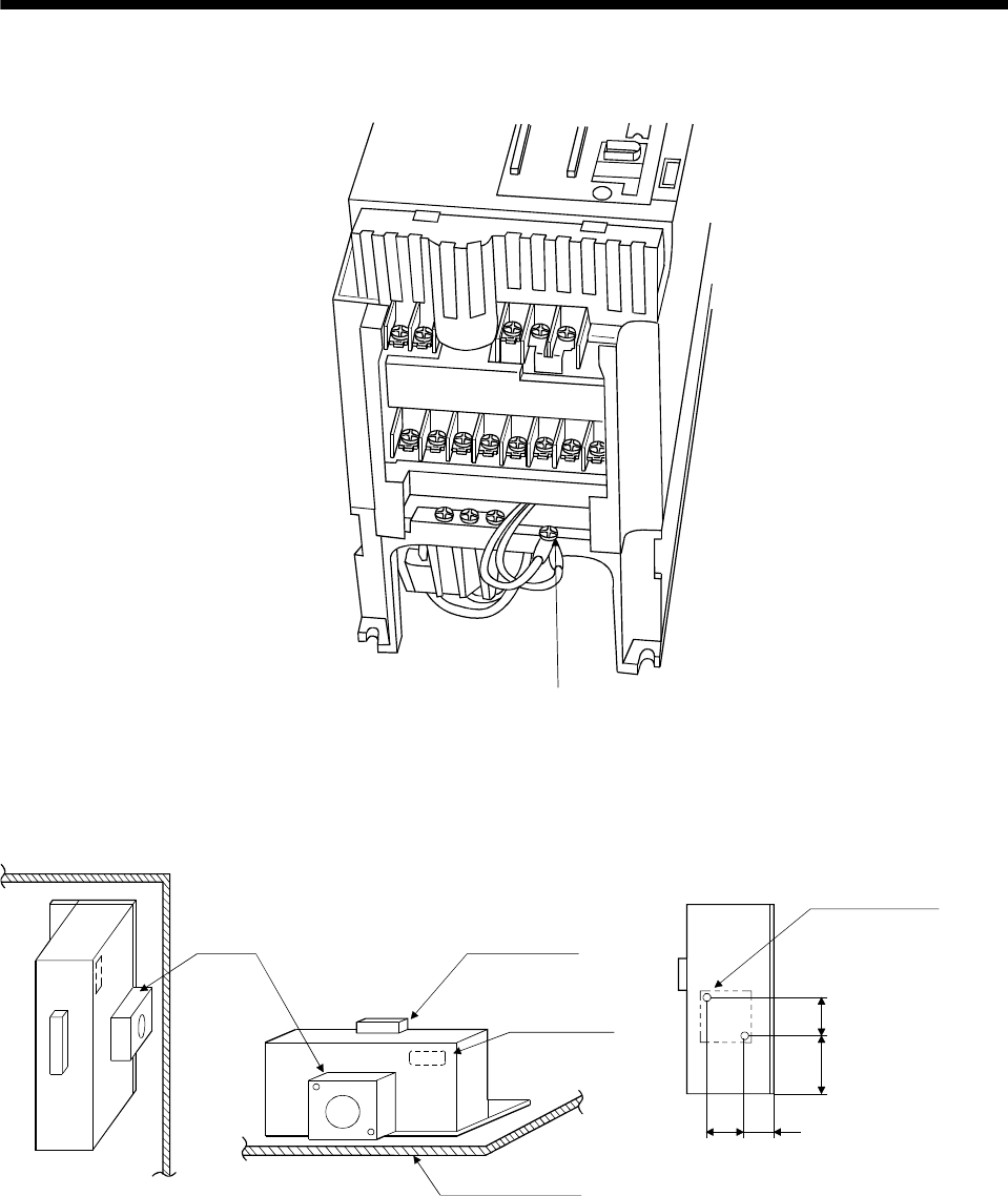
The drawing below shows the MR-J3-350T4 and MR-J3-500T(4). Refer to section 12.1 (6) Outline
drawings for the position of the fixing screw for MR-J3-700T(4).
Built-in regenerative resistor
lead terminal fixin
g
screw
For the MR-RB51, MR-RB3G-4, MR-RB5G-4, MR-RB34-4 or MR-RB54-4 install the cooling fan as
shown.
82.5 40 (1.58)
82.5
133
Cooling fan installation screw hole dimensions
2-M3 screw hole
(for cooling fan installation)
Depth 10 or less
(Screw hole already
machined)
Cooling fan Terminal block
Thermal relay
Installation surface
Horizontal installation
Vertical
installation
Top
Bottom
(3.25)
(5.24)
(3.25)
[Unit : mm(in)]


