


3 - 4
3. CC-LINK COMMUNICATION FUNCTIONS
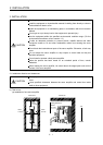
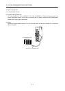
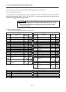
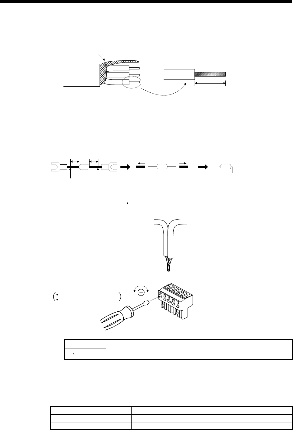
(4) How to wire the CC-Link connector (CN1)
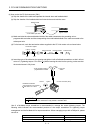
(a) Strip the sheath of the cable and separate the internal wires and braided shield.
(b) Strip the sheaths of the braided shield and internal wires and twist the cores.
3-core twisted pair cable
Braided shield
Approx. 10mm
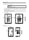
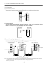
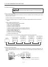
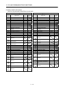
(c) Match and twist the wires and braided shield of the cable connected to the preceding axis or
programmable controller and the corresponding wires and braided shield of the cable connected to the
subsequent axis.
(d) For the last axis, work the termination resistor supplied to the CC-Link master unit as shown below.
Termination register
Cut
Remove sheath
Fold lead wire
Cut
Remove sheath
(10mm) (10mm)
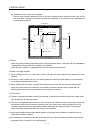
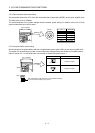
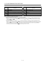
(e) Insert the core of the cable into the opening and tighten it with a flat-blade screwdriver so that it will not
come off. (Tightening torque: 0.5 to 0.6N
m) When inserting the wire into the opening, make sure that
the terminal screw is fully loose.
Loosen
Tighten
CC-Link connector (CN1)
To the next
station
Flat blade screwdriver
Tip thickness 0.4 to 0.6mm
Full wide 2.5 to 3.5mm
To the preceding station or
programmable controller
POINT
Do not solder the cores as it may cause a contact fault.
Use of a flat-blade torque screwdriver is recommended to manage the screw tightening torque. The
following table indicates the recommended products of the torque screwdriver for tightening torque
management and the flat-blade bit for torque screwdriver. When managing torque with a Phillips bit, please
consult us.
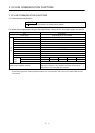
Product Model Manufacturer/Representative
Torque screwdriver N6L TDK Nakamura Seisakusho
Bit for torque screwdriver B-30, flat-blade, H3.5 X 73L Shiro Sangyo