


14 - 23
14. OPTIONS AND AUXILIARY EQUIPMENT
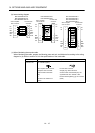
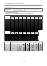
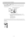
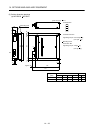
(a) MR-J3-350T or less
MR-J3-200T4 or less
Always remove the wiring from across P-D and fit the regenerative option across P-C.
The G3 and G4 terminals act as a thermal sensor. G3-G4 is disconnected when the regenerative option
overheats abnormally.
D
P
C
G4
G3
C
P
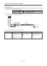
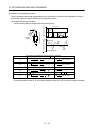
Servo amplifier
Regenerative option
(Note 2)
5m (16.4 ft) max.
Always remove the lead from across P-D.
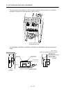
Cooling fan (Note 1)
Note 1. When using the MR-RB50, MR-RB3M-4, MR-RB3G-4 or MR-RB5G-4, forcibly cool it with
a cooling fan (92
92, minimum air flow : 1.0m
3
).
2. Make up a sequence which will switch off the magnetic contactor (MC) when abnormal
heating occurs.
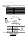
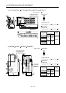
G3-G4 contact specifications
Maximum voltage: 120V AC/DC
Maximum current: 0.5A/4.8VDC
Maximum capacity: 2.4VA
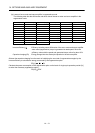
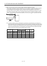
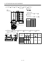
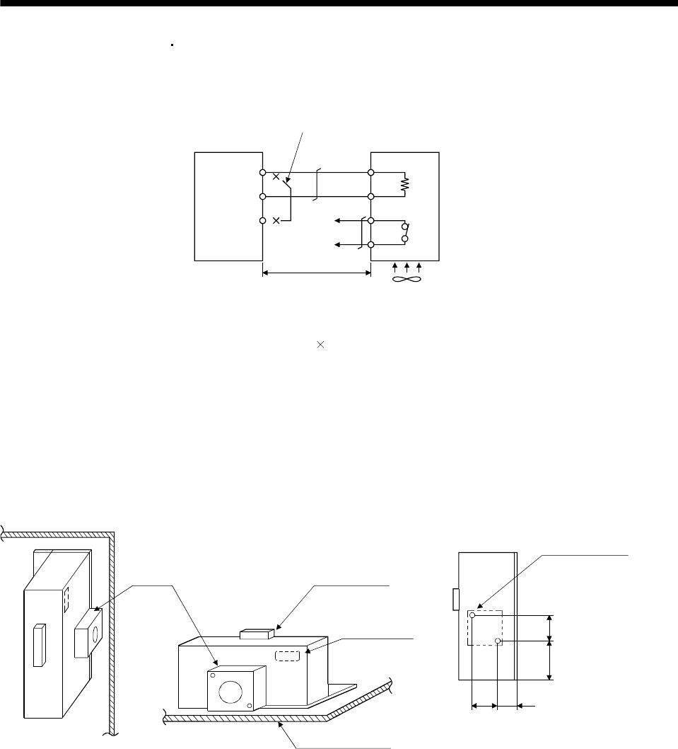
For the MR-RB50, MR-RB3M-4, MR-RB3G-4 or MR-RB5G-4 install the cooling fan as shown.
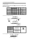
82.5 40 (1.58)
82.5
133
Cooling fan installation screw hole dimensions
2-M3 screw hole
(for cooling fan installation)
Depth 10 or less
(Screw hole already
machined)
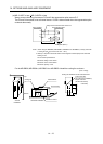
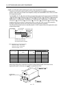
Cooling fan Terminal block
Thermal relay
Installation surface
Horizontal installation
Vertical
installation
Top
Bottom
(3.25)
(5.24)
(3.25)
[Unit : mm(in)]