


3 - 7
3. CC-LINK COMMUNICATION FUNCTIONS
3.3 Functions
3.3.1 Function block diagram
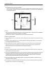
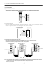
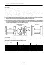
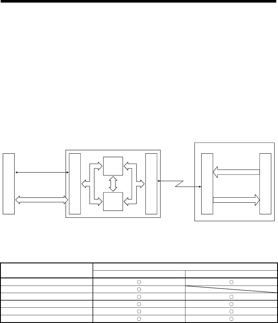
This section explains the transfer of I/O data to/from the servo amplifier in CC-Link, using function blocks.
(1) Between the master station and servo amplifier in the CC-Link system, link refresh is normally performed at
intervals of 3.5 to 18ms (512 points). The link scan time of link refresh changes with the communication
speed. For details, refer to the CC-Link system master/local unit user's manual.
(2) The I/O refresh and master station sequence program are executed asynchronously. Some programmable
controllers allow link scans to be synchronized with programmable controller scans.
(3) The FROM instruction from the buffer memory of the CC-Link system master/local unit is used to read data
from the servo amplifier, and the TO instruction is used to write data. Some programmable controllers allow
automatic refresh to be set to omit the FROM and TO instructions.
1) QJ61B11N
I/O signal
CPU
Buffer
memory
2) Buffer memory access
3) CC-Link
Ver.1.10-
compliant
cable
Input
Output
Servo amplifier
CC-Link interface
CC-Link interface
Servo amplifier CPU
Programmable controller
CPU
Interface with
programmable controller
Programmable controller
CC-Link unit
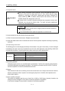
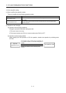
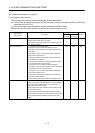
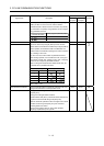
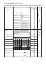
3.3.2 Functions
The following table lists the functions that may be performed from the programmable controller in the CC-Link
system in the CC-Link operation mode or test operation mode.
Operation mode
Item
CC-Link operation mode Test operation mode
Monitor
Operation
Parameter write
Parameter read
Point table data write
Point table data read