


6 - 23
6. PARAMETERS
No. Symbol Name and function Initial value Unit Setting range
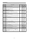
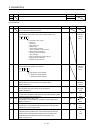
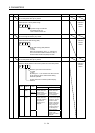
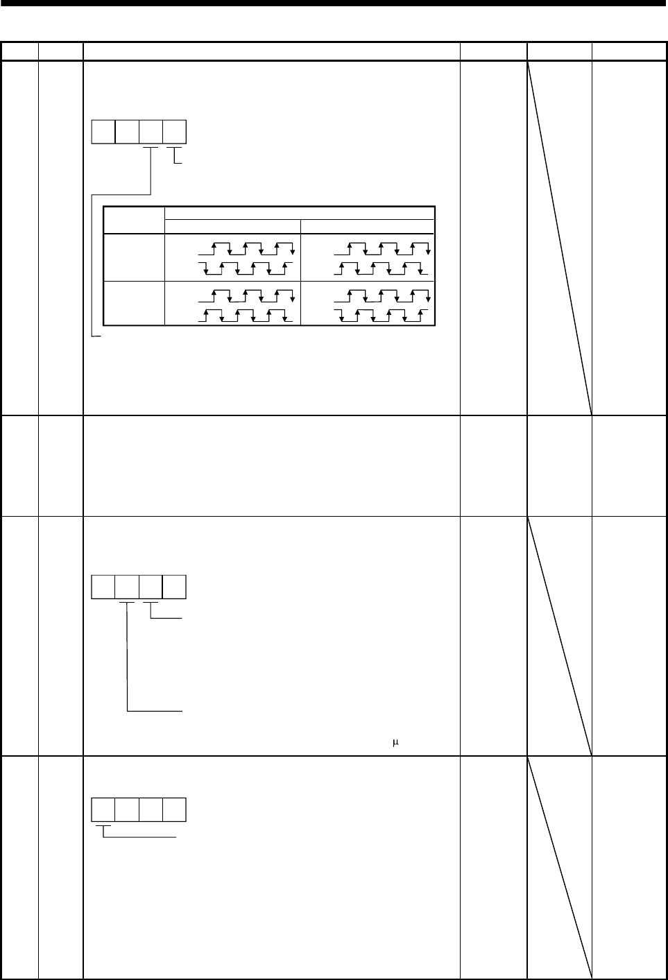
PC19 *ENRS Encoder output pulse selection
Use to select the, encoder output pulse direction and encoder output
pulse setting.
00
Servo motor rotation direction
Set value
CCW CW
0
1
A-phase
B-phase
A-phase
B-phase
A-phase
B-phase
A-phase
B-phase
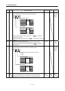
Encoder output pulse phase changing
Changes the phases of A, B-phase encoder pulses
output .
Encoder output pulse setting selection (refer to parameter No.PA15).
0: Output pulse designation
1: Division ratio setting
2: Ratio is automatically set to command pulse unit
Setting "2" makes the parameter No.PA15 (encoder output pulse)
setting invalid.
0000h Refer to
name and
function
column.
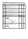
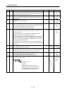
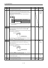
PC20 *SNO Station number setting
Used to specify the station number for RS-422 serial communication and
USB communication.
Always set one station to one axis of servo amplifier. If one station
number is set to two or more stations, normal communication cannot be
made.
0 station 0
to
31
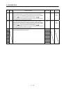
PC21 *SOP RS-422 communication function selection
Select the communication I/F and select the RS-422 communication
conditions.
00
RS-422 communication baud rate selection
0: 9600 [bps]
1: 19200 [bps]
2: 38400 [bps]
3: 57600 [bps]
4: 115200[bps]
RS-422 communication response delay time
0: Invalid
1: Valid, reply sent after delay time of 800 s or more
0000h Refer to
name and
function
column.
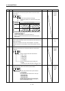
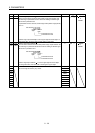
PC22 *COP1 Function selection C-1
Select the encoder cable communication system selection.
Encoder cable communication system selection
0: Two-wire type
1: Four-wire type
The following encoder cables are of 4-wire type.
MR-EKCBL30M-L
MR-EKCBL30M-H
MR-EKCBL40M-H
MR-EKCBL50M-H
The other encoder cables are all of 2-wire type.
Incorrect setting will result in an encoder alarm 1
(A16) or encoder alarm 2 (A20).
000
0000h Refer to the
name and
function
field.