4 - 42
4. SIGNALS AND WIRING
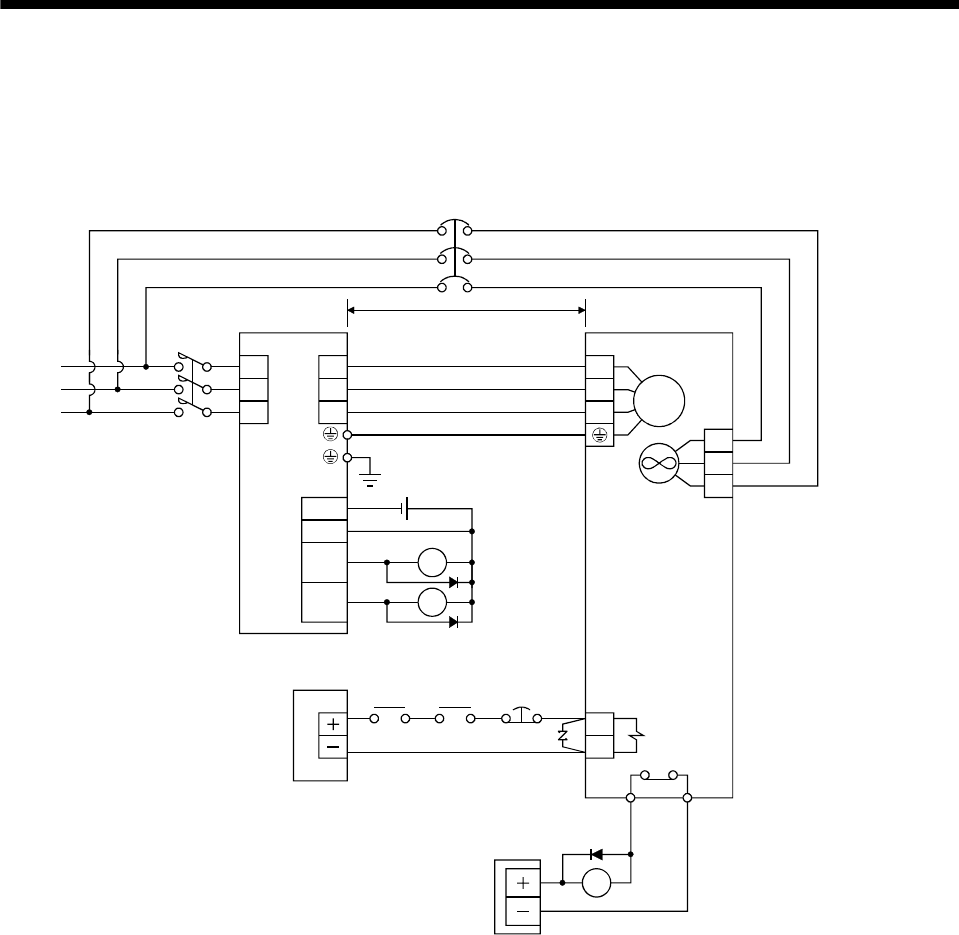
(3) HA-LP series servo motor
(a) Wiring diagrams
Refer to section 14.9 for the cables used for wiring.
1) 200V class
Servo motor
(Note 1)
Servo amplifier
U
V
W
B1
B2
U
V
W
24VDC power
supply for
electromagnetic
brake
50m or less
Forced
stop
(EMG)
Trouble
(ALM)
RA1
24VDC
ALM
DOCOM
DICOM
MBR
CN3
RA1
RA2
Electromagnetic
brake interlock
(MBR)
RA2
RA3
M
Cooling fan
(Note 2)
24VDC
power supply
OHS2OHS1 Servo motor
thermal relay
(Note 3)
L
1
L2
L
3
BU
BV
BW
TE
MC
(Note 4)
NFB
Note 1. There is no polarity in electromagnetic brake terminals B1 and B2.
2. There is no BW when the power supply of the cooling fan is a 1-phase.
3. Configure the power supply circuit which turns off the magnetic contactor after detection of servo motor thermal.
4. When using a servo motor with an electromagnetic brake, assign the electromagnetic brake interlock (MBR) to external
output signal in the parameters No.PD09 to PD11.


