


14 - 48
14. OPTIONS AND AUXILIARY EQUIPMENT
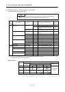
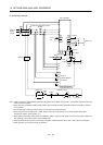
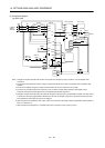
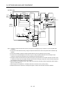
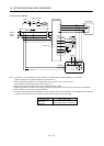
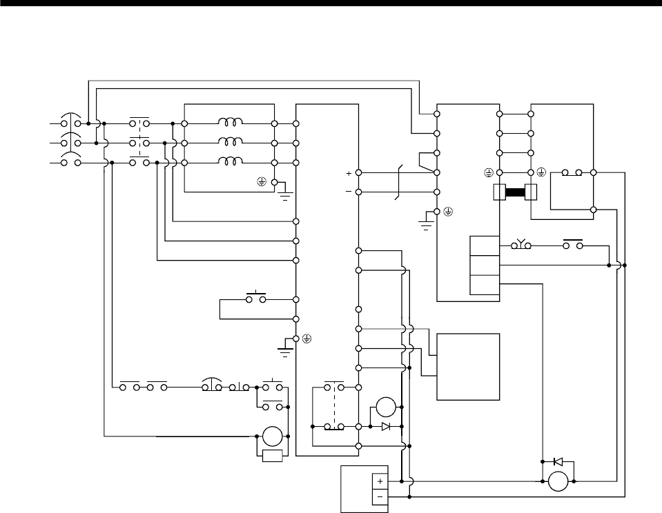
(3) Connection diagram
(a) 200V class
S2/L22
T2/L32
DOCOM
RA1
EMG
C
B
R/L11
S/L21
T/L31
R2/L1
R2/L12
S2/L2
N/L
P24
SD
RDYB
RDYA
RSO
SE
A
P/L
T2/L
3
R/L11
S/L21
T/MC1
RES
SD
L11
L21
P
N
U
V
W
EMG
RA1
RA2
U
V
W
0HS2
0HS1
CN2
MC
NFB
FR-CVL
FR-CV
MC
RA1 RA2
EMG
OFF
ON
RESET
SK
MC
P1
DICOM
Servo motorServo amplifier
Thermal
relay
(Note 2)
(Note 7)
(Note 6)
Servo system
controller
24VDC
power
supply
(Note 1)
(Note 1)
(Note 5)
(Note 3)
(Note 4)
(Note 1)
(Note 1)
3-phase
200 to
230VAC
Note 1. Configure a sequence that will shut off main circuit power at an emergency stop or at FR-CV or servo amplifier alarm
occurrence.
2. For the servo motor with thermal relay, configure a sequence that will shut off main circuit power when the thermal relay
operates.
3. For the servo amplifier, configure a sequence that will switch the servo on after the FR-CV is ready.
4. For the FR-CV, the RSO signal turns off when it is put in a ready-to-operate status where the reset signal is input.
Configure a sequence that will make the servo inoperative when the RSO signal is on.
5. Configure a sequence that will make a stop with the emergency stop input of the programmable controller if an alarm occurs
in the FR-CV. When the programmable controller does not have an emergency stop input, use the forced stop input of the
servo amplifier to make a stop as shown in the diagram.
6. When using the servo amplifier of 7kW or less, make sure to disconnect the wiring of built-in regeneration resistor (3.5kW or
less: P-D, 5k/7kW: P-C).
7. When using the servo amplifier of 11k to 22kW, make sure to connect P
1
and P. (Factory-wired.)