


63230-300-212 Chapter 6—Alarms
April 2001 Setpoint-Controlled Relay Functions
89
© 2001 Schneider Electric All Rights Reserved
This section describes some common motor management functions to which
the following information applies:
• Values that are too large to fit into the display may require scale factors.
For more information on scale factors, refer to “Changing Scale Factors”
on page 191 in Appendix B—Using the Command Interface.
• Relays can be configured as normal, latched, or timed. See “Relay Output
Operating Modes” on page 75 in Chapter 5—Input/Output Capabilities
for more information.
• When the alarm occurs, the circuit monitor operates any specified relays.
There are two ways to release relays that are in latched mode:
— Issue a command to de-energize a relay. See Appendix B—Using
the Command Interface on page 181 for instructions on using the
command interface, or
— Acknowledge the alarm in the high priority log to release the relays
from latched mode. From the main menu of the display, select View
Alarms > High Priority Log to view and acknowledge unacknowledged
alarms. See “Viewing Alarms” on page 41 for detailed instructions.
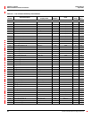
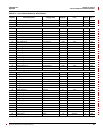
The list that follows shows the types of alarms available for some common
motor management functions:
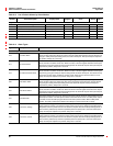
NOTE: Voltage base alarm setpoints depend on your system configuration.
Alarm setpoints for 3-wire systems are V
L-L
values while 4-wire systems are
V
L-N
values.
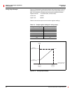
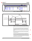
Undervoltage:
Pickup and dropout setpoints are entered in volts. The per-phase
undervoltage alarm occurs when the per-phase voltage is equal to or below
the pickup setpoint long enough to satisfy the specified pickup delay (in
seconds). The undervoltage alarm clears when the phase voltage remains
above the dropout setpoint for the specified dropout delay period.
Overvoltage:
Pickup and dropout setpoints are entered in volts. The per-phase overvoltage
alarm occurs when the per-phase voltage is equal to or above the pickup
setpoint long enough to satisfy the specified pickup delay (in seconds). The
overvoltage alarm clears when the phase voltage remains below the dropout
setpoint for the specified dropout delay period.
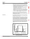
Unbalance Current:
Pickup and dropout setpoints are entered in tenths of percent, based on the
percentage difference between each phase current with respect to the
average of all phase currents. For example, enter an unbalance of 7% as 70.
The unbalance current alarm occurs when the phase current deviates from
the average of the phase currents, by the percentage pickup setpoint, for the
specified pickup delay. The alarm clears when the percentage difference
between the phase current and the average of all phases remains below the
dropout setpoint for the specified dropout delay period.
Types of Setpoint-Controlled
Relay Functions