


63230-300-212 Chapter 5—Input/Output Capabilities
April 2001 Solid-State KYZ Pulse Output
79
© 2001 Schneider Electric All Rights Reserved
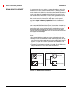
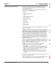
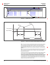
Most digital inputs in energy management systems use only two of the three
wires provided with a KYZ pulse initiator. This is called a 2-wire pulse initiator
application. Figure 5–3 shows a pulse train from a 2-wire pulse initiator
application.
In a 2-wire application, the pulse train looks like the alternating open and
closed states of a Form-A contact. Most 2-wire pulse initiator applications
use a Form-C contact, but tie into only one side of the Form-C contact where
the pulse is the transition from OFF to ON of that side of the Form-C relay. In
Figure 5–3, the transitions are marked as 1 and 2. Each transition represents
the time when the relay transitions from KZ to KY. Each time the relay
transitions, the receiver counts a pulse. The circuit monitor can deliver up to
25 pulses per second in a 2-wire application.
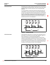
Figure 5–3: Two-wire pulse train
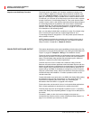
Some applications require the use of all three wires provided with the KYZ
pulse initiator. This is called a 3-wire pulse initiator application. Figure 5–4
shows a pulse train for a 3-wire pulse initiator application.
Three-wire KYZ pulses are the transitions between KY and KZ. These
transitions are the alternate contact closures of a Form-C contact. In Figure
5–4, the transitions are marked as 1, 2, 3, and 4. The receiver counts a pulse
at each transition. That is, each time the Form-C contact changes state from
KY to KZ, or from KZ to KY, the receiver counts a pulse.The circuit monitor
can deliver up to 50 pulses per second in a 3-wire application.
Figure 5–4: Three-wire pulse train
2-Wire Pulse Initiator
KY
KZ
Y
K
Z
12
T
3
3-Wire Pulse Initiator
KY
KZ
1 3 42
T
Y
K
Z
65