


63230-300-212 Chapter 5—Input/Output Capabilities
April 2001 Digital Inputs
71
© 2001 Schneider Electric All Rights Reserved
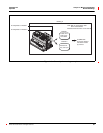
The circuit monitor can accept up to 16 digital inputs depending on the I/O
accessories you select. Digital inputs are used to detect digital signals. For
example, the digital input can be used to determine circuit breaker status,
count pulses, or count motor starts. Digital inputs can also be associated with
an external relay, which can trigger a waveform capture in the circuit monitor.
You can log digital input transitions as events in the circuit monitor’s on-board
alarm Log. The event is date and time stamped with resolution to the
millisecond, for sequence of events recording. The circuit monitor counts
OFF-to-ON transitions for each input, and you can reset this value using the
command interface.
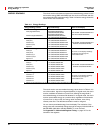
Digital inputs have four operating modes:
• Normal—Use the normal mode for simple on/off digital inputs. In normal
mode, digital inputs can be used to count KYZ pulses for demand and
energy calculation. Using the input pulse demand feature, you can map
multiple inputs to the same channel where the circuit monitor can total
pulses from multiple inputs (see“Input Pulse Demand Metering” on page
62 in Chapter 4—Metering Capabilities for more information). To
accurately count pulses, set the time between transitions from
OFF to ON
and ON to OFF to at least 20 milliseconds.
• Demand Interval Synch Pulse—you can configure any digital input to
accept a demand synch pulse from a utility demand meter (see “Demand
Synch Pulse Input” on page 72 of this chapter for more about this topic).
For each demand profile, you can designate only one input as a demand
synch input.
• Time Synch—you can configure one digital input to receive a signal from
a GPS receiver that provides a serial pulse stream in accordance to the
DCF-77 format to synchronize the internal clock of the circuit monitor.
• Conditional Energy Control—you can configure one digital input to
control conditional energy (see “Energy Readings” on page 64 in Chapter
4—Metering Capabilities for more about conditional energy).
To set up a digital input on the I/O extender, you must first define it from the
display. From the main menu, select Setup > I/O. Select the appropriate
digital input option. For example, if you are using IOX-2411 option of the I/O
Extender, select IOX-2411. For detailed instructions, see “Setting Up I/Os” on
page 23 in Chapter 3—Operation. Then using SMS, define the name and
operating mode of the digital input. The name is a 16-character label that
identifies the digital input. The operating mode is one of those listed above.
See the SMS online help for instructions on device set up of the circuit
monitor.
DIGITAL INPUTS