


Appendix A—Abbreviated Register Listing 63230-300-212
Register Listing April 2001
© 2001 Schneider Electric All Rights Reserved
136
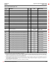
1325 Minimum Voltage, B-N D Volts/Scale 0 to 32,767
1326 Minimum Voltage, C-N D Volts/Scale 0 to 32,767
1327 Minimum Voltage, N-G E Volts/Scale 0 to 32,767
1328 Minimum Voltage, L-N Average D Volts/Scale 0 to 32,767
1329 Minimum Voltage Unbalance, A-B — 0.10% -1,000 to 1,000
1330 Minimum Voltage Unbalance, B-C — 0.10% -1,000 to 1,000
1331 Minimum Voltage Unbalance, C-A — 0.10% -1,000 to 1,000
1332 Minimum Voltage Unbalance, Max L-L — 0.10% -1,000 to 1,000
1333 Minimum Voltage Unbalance, A-N — 0.10% -1,000 to 1,000
1334 Minimum Voltage Unbalance, B-N — 0.10% -1,000 to 1,000
1335 Minimum Voltage Unbalance, C-N — 0.10% -1,000 to 1,000
1336 Minimum Voltage Unbalance, Max L-N — 0.10% -1,000 to 1,000
1340 Minimum Real Power, Phase A F kW/Scale -32,767 to 32,767
1341 Minimum Real Power, Phase B F kW/Scale -32,767 to 32,767
1342 Minimum Real Power, Phase C F kW/Scale -32,767 to 32,767
1343 Minimum Real Power, Total F kW/Scale -32,767 to 32,767
1344 Minimum Reactive Power, Phase A F kVAr/Scale -32,767 to 32,767
1345 Minimum Reactive Power, Phase B F kVAr/Scale -32,767 to 32,767
1346 Minimum Reactive Power, Phase C F kVAr/Scale -32,767 to 32,767
1347 Minimum Reactive Power, Total F kVAr/Scale -32,767 to 32,767
1348 Minimum Apparent Power, Phase A F kVA/Scale -32,767 to 32,767
1349 Minimum Apparent Power, Phase B F kVA /Scale -32,767 to 32,767
1350 Minimum Apparent Power, Phase C F kVA /Scale -32,767 to 32,767
1351 Minimum Apparent Power, Total F kVA /Scale -32,767 to 32,767
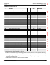
1360 Minimum True Power Factor, Phase A — 0.001 1,000 -100 to 100
1361 Minimum True Power Factor, Phase B — 0.001 1,000 -100 to 100
1362 Minimum True Power Factor, Phase C — 0.001 1,000 -100 to 100
1363 Minimum True Power Factor, Total — 0.001 1,000 -100 to 100
1364 Minimum Alternate True Power Factor, Phase A — 0.001 0 to 2,000
1365 Minimum Alternate True Power Factor, Phase B — 0.001 0 to 2,000
1366 Minimum Alternate True Power Factor, Phase C — 0.001 0 to 2,000
1367 Minimum Alternate True Power Factor, Total — 0.001 0 to 2,000
1368 Minimum Displacement Power Factor, Phase A — 0.001 1,000 -100 to 100
1369 Minimum Displacement Power Factor, Phase B — 0.001 1,000 -100 to 100
1370 Minimum Displacement Power Factor, Phase C — 0.001 1,000 -100 to 100
1371 Minimum Displacement Power Factor, Total — 0.001 1,000 -100 to 100
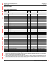
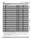
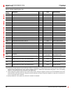
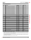
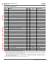
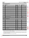
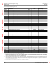
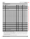
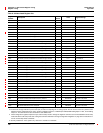
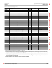
Table A–3:Abbreviated Register List
Register
Number
Description
Scale
Factor
Units Register Range
See “How Power Factor is Stored in the Register” on page 128.
The alternate storage method for power factor (PF) is useful for outputting PF on analog outputs. The PF value is stored as a positive value
between 0 and 2, centered around 1 (unity). A value of 0 lagging maps to0; -0.999 maps to 0.999;0.999 leadingmaps to 1.001; and 0 leading
maps to 2. The alternate PF is also stored with a scale factor 0.001.
These configuration registers require that you enter the setup mode to change the register’s contents. Issue command 9020 to enter setup
mode and 9021 to exit setup mode. See “Using the Command Interface to Change Configuration Registers” on page 187 for instructions on
howtousethesetup-modecommands.
Quantity available for 4-wire system only. Value set to -32,768 if not available.