


Appendix A—Abbreviated Register Listing 63230-300-212
Register Listing April 2001
© 2001 Schneider Electric All Rights Reserved
154
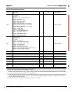
2380 to 2399
Input Channel #10
Same as registers 2200 to 2219 except for Channel #10
2400
Input Register, Generic Channel #1
Register selected for generic demand calculation
——1,000 to 32,767
2401
Unit Code, Generic Channel #1
For software use only
——0to99
2402
Scale Code, Generic Channel #1 ——-3 to 3
2403 Last Demand, Generic Channel #1 ——0to32,767
2404 Present Demand, Generic Channel #1 ——0to32,767
2405 Running Average, Demand Generic Channel #1 ——0to32,767
2406
Peak Demand, Generic Channel #1
Channel #1 peak demand since last Min/Max demand reset
——0to32,767
2407 to 2410
Peak Demand Date/Time, Generic Channel #1
Date/Time of peak demand since last peak demand reset
— See Template See Template
2411
Minimum Demand, Generic Channel #1
Channel #1 minimum since last Min/Max demand reset
——0to32,767
2412 to 2415
Minimum Demand Date/Time, Generic Channel #1
Date/Time of minimum demand since last Min/Max reset
— See Template See Template
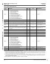
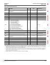
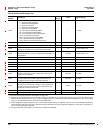
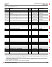
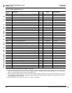
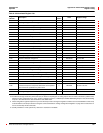
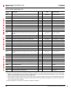
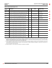
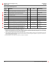
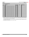
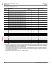
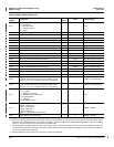
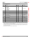
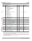
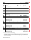
Table A–3:Abbreviated Register List
Register
Number
Description
Scale
Factor
Units Register Range
See “How Power Factor is Stored in the Register” on page 128.
The alternate storage method for power factor (PF) is useful for outputting PF on analog outputs. The PF value is stored as a positive value
between 0 and 2, centered around 1 (unity). A value of 0 lagging maps to0; -0.999 maps to 0.999;0.999 leadingmaps to 1.001; and 0 leading
maps to 2. The alternate PF is also stored with a scale factor 0.001.
These configuration registers require that you enter the setup mode to change the register’s contents. Issue command 9020 to enter setup
mode and 9021 to exit setup mode. See “Using the Command Interface to Change Configuration Registers” on page 187 for instructions on
howtousethesetup-modecommands.
Quantity available for 4-wire system only. Value set to -32,768 if not available.