


Chapter 6—Alarms 63230-300-212
Alarm Conditions and Alarm Numbers April 2001
© 2001 Schneider Electric All Rights Reserved
96
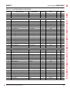
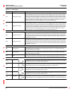
Digital
01 End of incremental energy interval End Inc Enr Int N/A ——070
02 End of power demand interval End Power Dmd Int N/A ——070
03 End of 1-second update cycle End 1s Cyc N/A ——070
04 End of 100ms update cycle End 100ms Cyc N/A ——070
05 Power up/Reset Pwr Up/Reset N/A ——070
06-40 Reserved for custom alarms —————
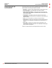
Table 6–4: Alarm Types
Type Description Operation
Standard Speed
010 Over Value Alarm
If the test register value exceeds the setpoint long enough to satisfy the pickup delay period, the
alarm condition will be true. When the value in the test register falls below the dropout setpoint long
enough to satisfy the dropout delay period, the alarm will dropout. Pickup and dropout setpoints
are positive, delays are in seconds.
011 Over Power Alarm
If the absolute value in the test register exceedsthe setpoint long enough to satisfy the pickup delay
period, the alarm condition will be true. When the value in the test register falls below the dropout
setpoint long enough to satisfythe dropout delay period, the alarm will dropout. Pickup and dropout
setpoints are positive, delays are in seconds.
012 Over Reverse Power Alarm
If the absolute value in the test register exceedsthe setpoint long enough to satisfy the pickup delay
period, the alarm condition will be true. When the value in the test register falls below the dropout
setpoint long enough to satisfy the dropout delay period, the alarm will dropout. This alarm will only
hold true for reverse power conditions. Positive power values will not cause the alarm to occur.
Pickup and dropout setpoints are positive, delays are in seconds.
020 Under Value Alarm
If the test register value is below the setpoint long enough to satisfy the pickup delay period, the
alarm condition will be true. When the value in the test register rises above the dropout setpoint
long enough to satisfy the dropout delay period, the alarm will dropout. Pickup and dropout
setpoints are positive, delays are in seconds.
021 Under Power Alarm
If the absolute value inthe test register is below the setpoint long enough to satisfy the pickup delay
period, the alarm condition will be true. When the value in the test register rises above the dropout
setpoint long enough to satisfythe dropout delay period, the alarm will dropout. Pickup and dropout
setpoints are positive, delays are in seconds.
051 Phase Reversal
The phase reversal alarm will occur whenever the phase voltage waveform rotation differs from the
default phase rotation. The ABC phase rotation is assumed to be normal. If a CBA phase rotation
is normal, the user should reprogram the circuit monitor’s phase rotation ABC to CBA phase
rotation. The pickup and dropout setpoints and delays for phase reversal do not apply.
052 Phase Loss, Voltage
The phase loss voltage alarm will occur when any one or two phase voltages (but not all) fall to the
pickup value and remain at or below the pickup value long enough to satisfy the specified pickup
delay. When all of the phases remain at or above the dropout value for the dropout delay period, or
when all of the phases drop below the specified phase loss pickup value, the alarm will dropout.
Pickup and dropout setpoints are positive, delays are in seconds.
053 Phase Loss, Current
The phase loss current alarm will occur when any one or two phase currents (but not all) fall to the
pickup value and remain at or below the pickup value long enough to satisfy the specified pickup
delay. When all of the phases remain at or above the dropout value for the dropout delay period, or
when all of the phases drop below the specified phase loss pickup value, the alarm will dropout.
Pickup and dropout setpoints are positive, delays are in seconds.
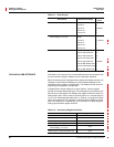
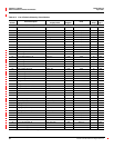
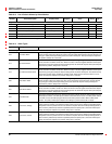
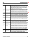
Table 6–3: List of Default Alarms by Alarm Number
Alarm
Number
Alarm Description
Abbreviated
Display Name
Test
Register
Units
Scale
Group
Alarm
Type
Alarm Types are described in Table 6–4 on page 96.