


63230-300-212 Appendix A—Abbreviated Register Listing
April 2001 Register Listing
147
© 2001 Schneider Electric All Rights Reserved
1865
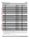
Short Demand Interval, Input Pulse Metering
Sets the interval for a running average demand calculation of
short duration.
— Seconds 0 to 60, Default = 15
1866 Time Elapsed in Interval, Input Pulse Metering — Seconds 0 to 3,600
1867 Time Elapsed in Subinterval, Input Pulse Metering — Seconds 0 to 3,600
1868 Interval Count, Input Pulse Metering — 1.0 0 to 32,767
1869 Subinterval Count, Input Pulse Metering — 1.0 0 to 60
1870 to 1873 Min/Max Reset Date/Time, Input Pulse Metering — See Template See Template
1874 Min/Max Reset Count, Input Pulse Metering — 1.0 0 to 32,767
1880
Demand Calculation Mode, Generic Group 1
0 = Thermal Demand (default)
1 = Timed Interval Sliding Block
2=TimedIntervalBlock
4 = Timed Interval Rolling Block
8 = Input Synchronized Block
16 = Input Synchronized Rolling Block
32 = Command Synchronized Block
64 = Command Synchronized Rolling Block
128 = Clock Synchronized Block
256 = Clock Synchronized Rolling Block
512 = Slave to Power Demand Interval
1024 = Slave to Incremental Energy Interval
——0to1024
1881
Demand Interval, Generic Group 1 — Minutes 1 to 60, Default = 15
1882
Demand Subinterval, Generic Group 1 — Minutes 1 to 60, Default = 1
1883
Demand Sensitivity, Generic Group 1
Adjusts the sensitivity of the thermal demand calculation.
— 1% 1to99,Default=90
1885
Short Demand Interval, Generic Group 1
Sets the interval for a running average demand calculation of
short duration.
— Seconds 0 to 60, Default = 15
1886 Time Elapsed in Interval, Generic Group 1 — Seconds 0 to 3,600
1887 Time Elapsed in Subinterval, Generic Group 1 — Seconds 0 to 3,600
1888 Interval Count, Generic Group 1 — 1.0 0 to 32,767
1889 Subinterval Count, Generic Group 1 — 1.0 0 to 60
1890 to 1893 Min/Max Reset Date/Time, Generic Group 1 — See Template See Template
1894 Min/Max Reset Count, Generic Group 1 — 1.0 0 to 32,767
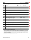
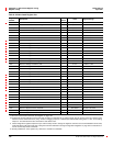
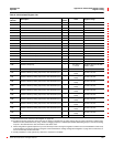
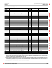
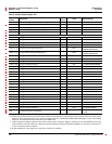
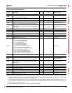
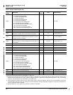
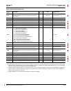
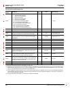
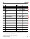
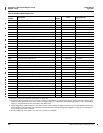
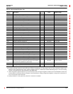
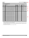
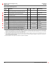
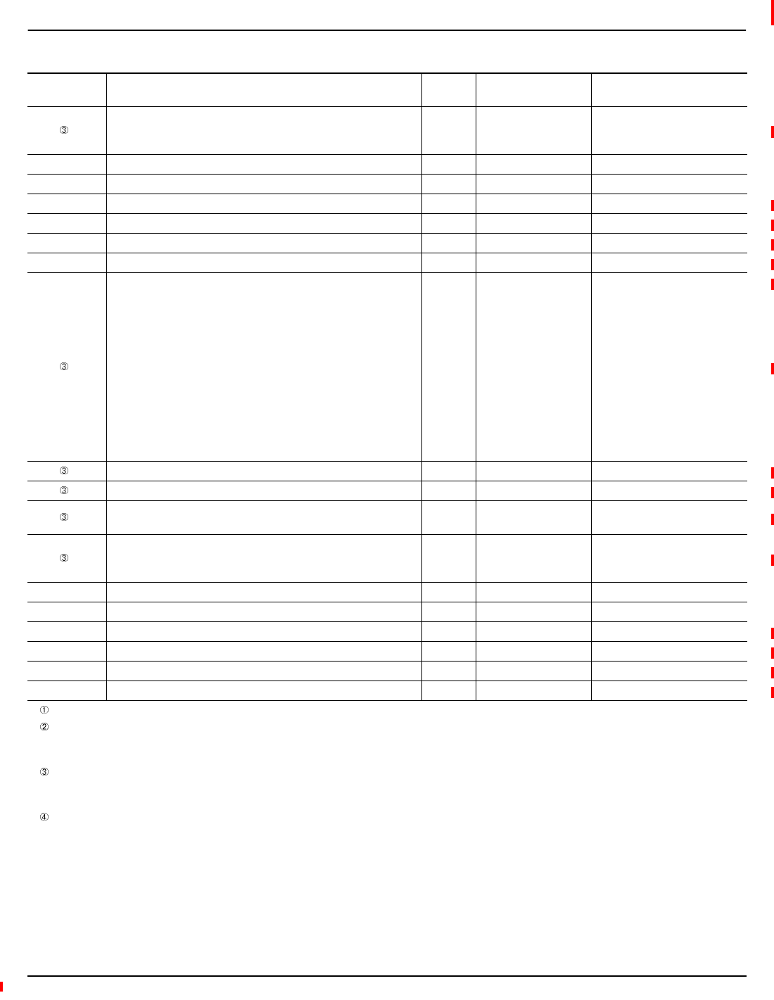
Table A–3:Abbreviated Register List
Register
Number
Description
Scale
Factor
Units Register Range
See “How Power Factor is Stored in the Register” on page 128.
The alternate storage method for power factor (PF) is useful for outputting PF on analog outputs. The PF value is stored as a positive value
between 0 and 2, centered around 1 (unity). A value of 0 lagging maps to 0; -0.999 maps to 0.999;0.999 leading maps to 1.001; and 0 leading
maps to 2. The alternate PF is also stored with a scale factor 0.001.
These configuration registers require that you enter the setup mode to change the register’s contents. Issue command 9020 to enter setup
mode and 9021 to exit setup mode. See “Using the Command Interface to Change Configuration Registers” on page 187 for instructions on
how to use the setup-mode commands.
Quantity available for 4-wire system only. Value set to -32,768 if not available.