


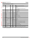
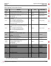

Appendix A—Abbreviated Register Listing 63230-300-212
Register Listing April 2001
© 2001 Schneider Electric All Rights Reserved
172
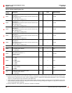
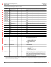
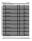
Base
IO Point Type — 400to499
First digit (4) indicates point is analog output.
Second digit indicates the range of analog I/O values (used without
units).
5=4to20
Third digit indicates the digital resolution of the I/O hardware. The
user must select from one of these standard ranges.
2 = 12-Bit , unipolar
Base + 1
IO Point Label
Alpha-
Numeric
— 16-character label
Base + 12
Output Enable — 0to1
Analog output control
0 = Enable (default)
1=Disable
Base + 14
Lower Limit Analog
Value
— 0to±327
Lower limit of the analog output value. Default value based on IO
Point Type.
Base + 15
Upper Limit Analog
Value
— 0to±327
Upper limit of the analog output value. Default value based on IO
Point Type.
Base + 16
Lower Limit Register
Value
— 0to±32,767
Lower limit of the register value associated with the lower limit of the
analog output value.
Base + 17
Upper Limit Register
Value
— 0to±32,767
Upper limit of the register value associated with the upper limit of
the analog output value.
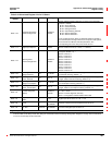
Base + 18
Reference Register
Number
—
1,000 to
32,767
Register location of value upon which to base the analog output.
Base + 19
User Gain Adjustment 0.0001
8000 to
12,000
Analog output user gain adjustment in 100ths of a percent. Default
= 10,000.
Base + 20
User Offset
Adjustment
— 0 to ±30000
Analog output user offset adjustment in Bit s of digital resolution.
Default = 0.
Base + 23
Lower Limit Digital
Value
— 0to±32,767
Lower limit of the digital value associated with the lower limit of the
analog output value. Value based on IO Point Type.
Base + 24
Upper Limit Digital
Value
— 0to±32,767
Upper limit of the digital value associated with the upper limit of the
analog output value. Value based on IO Point Type.
Base + 25 Present Analog Value 0.01 0 to ±32,767
Analogvalueexpectedtobepresentattheoutputterminalsofthe
analog output module.
Base + 26
Present Raw
(Register) Value
— 0 to ±32,767 Value in Reference Register.
Base + 27 Calibration Offset — 0 to ±32,767 Analog output offset adjustment in Bit s of digital resolution.
Base + 28
Calibration Gain
(Voltage)
0.0001
8000 to
12,000
Analog output gain adjustment in 100ths of a percent.
Table A–4:Abbreviated Register List for I/O Status
Register
Number
Name Units Range Description
These configuration registers require that you enter the setup mode to change the register’s contents. Issue command 9020 to enter setup
mode and 9021 to exit setup mode. See “Using the Command Interface to Change Configuration Registers” on page 187 for instructions
on how to use the setup-mode commands.