


63230-300-212 Appendix A—Abbreviated Register Listing
April 2001 Register Listing
161
© 2001 Schneider Electric All Rights Reserved
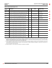
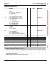
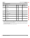
3241
Harmonic Magnitude Format
0 = % of Fundamental (default)
1=%ofRMS
——0to1
3242
Harmonic Refresh Interval — Seconds 10 to 60, Default = 30
3243 Time Remaining Until Harmonic Refresh — Seconds 10 to 60
3270 to 3273 Minimum/Maximum Reset Date/Time — See Template See Template
3274 to 3277 Accumulated Energy Reset Date/Time — See Template See Template
3278 to 3281 Conditional Energy Reset Date/Time — See Template See Template
3282 to 3285 Incremental Energy Reset Date/Time — See Template See Template
3286 to 3289 Input Metering Accumulation Reset Date/Time — See Template See Template
3290 to 3293 Accumulated Energy Preset Date/Time — See Template See Template
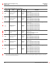
3299
Average/Min/Max Log Number of Data Items
Number of Quantities for which Average/Min/Max calculations
are made and logged.
— 125
3300
Average/Min/Max Log Interval
Must be evenly divisible into 1440.
— Minutes 1 to 1440, Default = 60
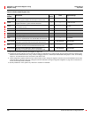
3301
Average/Min/Max Log Channel #1 Meter Register
0 = No calculation for this channel
——
0, 1100 to 2999; Default =
1100 Current, Phase A
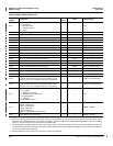
3302
Average/Min/Max Log Channel #2 Meter Register
0 = No calculation for this channel
——
0, 1100 to 2999; Default =
1101 Current, Phase B
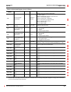
3303
Average/Min/Max Log Channel #3 Meter Register
0 = No calculation for this channel
——
0, 1100 to 2999; Default =
1102 Current, Phase C
3304
Average/Min/Max Log Channel #4 Meter Register
0 = No calculation for this channel
——
0, 1100 to 2999; Default =
1103 Current, Neutral
3305
Average/Min/Max Log Channel #5 Meter Register
0 = No calculation for this channel
——
0, 1100 to 2999; Default =
1104 Current, Ground
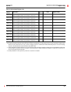
3306
Average/Min/Max Log Channel #6 Meter Register
0 = No calculation for this channel
——
0, 1100 to 2999; Default =
1120 Voltage, A-B
3307
Average/Min/Max Log Channel #7 Meter Register
0 = No calculation for this channel
——
0, 1100 to 2999; Default =
1121 Voltage B-C
3308
Average/Min/Max Log Channel #8 Meter Register
0 = No calculation for this channel
——
0, 1100 to 2999; Default =
1122 Voltage C-A
3309
Average/Min/Max Log Channel #9 Meter Register
0 = No calculation for this channel
——
0, 1100 to 2999; Default =
1127 Voltage N-G
3310
Average/Min/Max Log Channel #10 Meter Register
0 = No calculation for this channel
——
0, 1100 to 2999; Default =
1143 Real Power, Total
3311
Average/Min/Max Log Channel #11 Meter Register
0 = No calculation for this channel
——
0, 1100 to 2999; Default =
1147 Reactive Power, Total
3312
Average/Min/Max Log Channel #12 Meter Register
0 = No calculation for this channel
——
0, 1100 to 2999; Default =
1151 Apparent Power, Total
3313
Average/Min/Max Log Channel #13 Meter Register
0 = No calculation for this channel
——
0, 1100 to 2999; Default =
1163 True Power Factor, Total
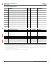
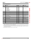
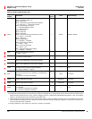
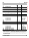
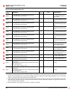
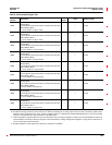
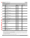
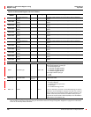
Table A–3:Abbreviated Register List
Register
Number
Description
Scale
Factor
Units Register Range
See “How Power Factor is Stored in the Register” on page 128.
The alternate storage method for power factor (PF) is useful for outputting PF on analog outputs. The PF value is stored as a positive value
between 0 and 2, centered around 1 (unity). A value of 0 lagging maps to 0; -0.999 maps to 0.999;0.999 leading maps to 1.001; and 0 leading
maps to 2. The alternate PF is also stored with a scale factor 0.001.
These configuration registers require that you enter the setup mode to change the register’s contents. Issue command 9020 to enter setup
mode and 9021 to exit setup mode. See “Using the Command Interface to Change Configuration Registers” on page 187 for instructions on
how to use the setup-mode commands.
Quantity available for 4-wire system only. Value set to -32,768 if not available.