


63230-300-212 Chapter 3—Operation
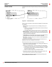
April 2001 Performing a Wiring Check
49
© 2001 Schneider Electric All Rights Reserved
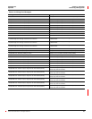
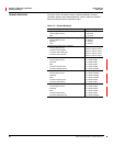
Suspected error: Polarity on V3–1VT PolarityofV3–1 VT could be reversed. Check polarity.
Suspected error: Check V1 input, may be V2 VT Phase 2 VT may actually be connected to input V1.
Suspected error: Check V2 input, may be V3 VT Phase 3 VT may actually be connected to input V12
Suspected error: Check V3 input, may be V1 VT Phase 1 VT may actually be connected to input V3.
Suspected error: Check V1 input, may be V3 VT Phase 3 VT may actually be connected to input V1.
Suspected error: Check V2 input, may be V1 VT Phase 1 VT may actually be connected to input V2.
Suspected error: Check V3 input, may be V2 VT Phase 2 VT may actually be connected to input V3.
I1 load current less than 1% CT Metered current on I1 less than 1% of CT. Test could not continue.
I2 load current less than 1% CT Metered current on I2 less than 1% of CT. Test could not continue.
I3 load current less than 1% CT Metered current on I3 less than 1% of CT. Test could not continue.
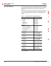
I1 phase angle out of range. Cause of error unknown.
I1 phase angle is out of expected range. Cause of error unable to
be determined.
I2 phase angle out of range. Cause of error unknown
I2 phase angle is out of expected range. Cause of error unable to
be determined.
I3 phase angle out of range. Cause of error unknown.
I3 phase angle is out of expected range. Cause of error unable to
be determined.
Suspected error: Reverse polarity on I1 CT. Polarity of I1 CT could be reversed. Check polarity.
Suspected error: Reverse polarity on I2 CT Polarity of I2 CT could be reversed. Check polarity.
Suspected error: Reverse polarity on I3 CT Polarity of I3 CT could be reversed. Check polarity.
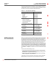
Suspected error: Check I1 input, may be I2 CT Phase 2 CT may actually be connected to input I1.
Suspected error: Check I2 input, may be I3 CT Phase 3 CT may actually be connected to input I2.
Suspected error: Check I3 input, may be I1 CT Phase 1 CT may actually be connected to input I3.
Suspected error: Check I1 input, may be I3 CT Phase 3 CT may actually be connected to input I1.
Suspected error: Check I2 input, may be I1 CT Phase 1 CT may actually be connected to input I2.
Suspected error: Check I3 input, may be I2 CT Phase 2 CT may actually be connected to input I3.
Suspected error: Check I1 input, may be I2 CT with reverse polarity
Phase 2 CT may actually be connected to input I1, and the CT
polarity may also be reversed.
Suspected error: Check I2 input, may be I3 CT with reverse polarity
Phase 3 CT may actually be connected to input I21, and the CT
polarity may also be reversed.
Suspected error: Check I3 input, may be I1 CT with reverse polarity
Phase 1 CT may actually be connected to input I3, and the CT
polarity may also be reversed.
Suspected error: Check I1 input, may be I3 CT with reverse polarity
Phase 3 CT may actually be connected to input I1, and the CT
polarity may also be reversed.
Suspected error: Check I2 input, may be I1 CT with reverse polarity
Phase 1 CT may actually be connected to input I2, and the CT
polarity may also be reversed.
Suspected error. Check I3 input, may be I2 CT with reverse polarity
Phase 2 CT may actually be connected to input I3, and the CT
polarity may also be reversed.
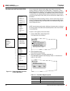
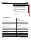
Table 3–12: Wiring Error Messages
Message Description