


63230-300-212 Appendix A—Abbreviated Register Listing
April 2001 Register Listing
171
© 2001 Schneider Electric All Rights Reserved
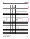
Base + 26 Count —
0to
99,999,999
Number of times output has transitioned from Off to On
Base + 28 On Time Seconds
0to
99,999,999
Duration that digital output has been On
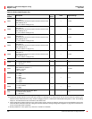
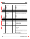
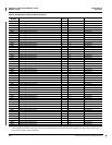
Analog Input Template
Base
IO Point Type — 300 to 399
First digit (3) indicates point is analog input.
Second digit indicates the range of analog I/O values (used without
units)
1=0to5
5=4to20
Third digit indicates the digital resolution of the I/O hardware. The
user must select from one of these standard ranges.
2 = 12-Bit , unipolar
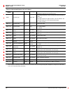
Base + 1
IO Point Label
Alpha-
Numeric
— 16-character label
Base + 9
Units Code — 0to99
Analog input units code placeholder for a code used by software to
identify the SI units of the analog input being metered, i.e. kW, V,
etc.
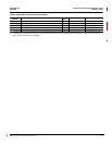
Base + 10
Scale Code — -3 to 3 Analog input scale code.
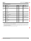
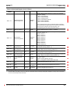
Base + 12
Analog Input Minimum — 0 to ±32,767
Minimum value of the scaled register value for the analog input.
(Only if Metering Register Number is not 0.)
Base + 13
Analog Input
Maximum
— 0 to ±32,767
Maximum value of the scaled register value for the analog input.
(Only if Metering Register Number is not 0.)
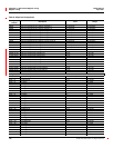
Base + 14
Lower Limit Analog
Value
— 0to±327
Lower limit of the analog input value. Default value based on IO
Point Type.
Base + 15
Upper Limit Analog
Value
— 0to±327
Upper limit of the analog input value. Default value based on IO
Point Type.
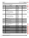
Base + 16
Lower Limit Register
Value
— 0 to ±32,767
Lower limit of the register value associated with the lowerlimit of the
analog input value.
Base + 17
Upper Limit Register
Value
— 0 to ±32,767
Upper limit of the register value associated with the upper limit of
the analog input value.
Base + 18
Metering Register
Number
—
0, 1190 to
1199
Register where Present Scaled Value is copied. This register is
included in the Min/Max determination for metered values.
Base + 19
User Gain Adjustment 0.0001
8,000 to
12,000
Analog input user gain adjustment in 100ths of a percent. Default =
10,000.
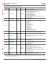
Base + 20
User Offset
Adjustment
— 0 to ±30,000
Analog input user offset adjustment in Bits of digital resolution.
Default = 0.
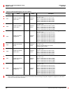
Base + 22
IO Point Diagnostic
Bitmap
—
0x0000 to
0x0007
IO Point Diagnostic Bitmap:
0 = OK, 1 = Error
Bit00=IOPointdiagnosticsummary
Bit 01 = Configuration invalid to default value used
Bit 02 = M-Bus communications error Remaining bits not used.
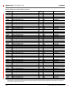
Base + 23
Lower Limit Digital
Value
— 0 to ±32,767
Lower limit of the digital value associated with the lower limit of the
analog input value. Value based on IO Point Type.
Base + 24
Upper Limit Digital
Value
— 0 to ±32,767
Upper limit of the digital value associated with the upper limit of the
analog input value. Value based on IO Point Type.
Base + 25 Present Raw Value — 0to±32,767 Rawdigitalvaluereadfromanaloginput.
Base + 26 Present Scaled Value — 0 to ±32,767
Raw value corrected by calibration gain and offset adjustments and
scaled based on range of register values.
Analog Output Template
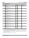
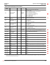
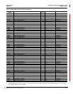
Table A–4:Abbreviated Register List for I/O Status
Register
Number
Name Units Range Description
These configuration registers require that you enter the setup mode to change the register’s contents. Issue command 9020 to enter setup
mode and 9021 to exit setup mode. See “Using the Command Interface to Change Configuration Registers” on page 187 for instructions
on how to use the setup-mode commands.