


Appendix A—Abbreviated Register Listing 63230-300-212
Register Listing April 2001
© 2001 Schneider Electric All Rights Reserved
160
3227
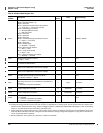
Operating Mode Parameters
Mode Control Bits (Default = 0)
Bit 00 = Reserved
Bit 01 = Reactive Energy & Demand Accumulation
0 = Fund. Only ; 1 = Harmonics Included
Bit 02 = VAR/PF Sign Convention
0 = Standard IEEE Convention
1 = CM1 Convention
Bit 03 = Reserved
Bit 04 = Reserved
Bit 05 = Reserved
Bit 06 = Conditional Energy Accumulation Control
0 = Inputs; 1 = Command
Bit 07 = Reserved
Bit 08 = Display Setup
0=Enabled;1=Disabled
Bit 09 = Normal Phase Rotation
0 = ABC; 1 = CBA
Bit10=LargeorSmallTHD
0 = THD; 1 = thd
Bit 11 = Generate Phase Loss Voltage
0 = Disabled; 1 = Enabled
— Bitmap 0x0000 to 0x0FFF
3228
Metered Phase Rotation Direction
0 = ABC; 1 = CBA
——0to1
3229
Incremental Energy Interval
0 = Continuous Accumulation
— Minutes 0 to 1440, Default = 60
3230
Incremental Energy Interval Start Time
Value is time represented in minutes from midnight
— Minutes 0 to 1440, Default = 0
3231
Incremental Energy Interval End Time
Value is time represented in minutes from midnight
— Minutes 0 to 1440, Default = 1440
3232
Energy Accumulation Mode
Real and Reactive Energy Accumulation Mode
0 = Absolute (default); 1 = Signed
——0to1
3233
Peak Current Demand Over Last Year
Entered by the user for use in calculation of Total Demand
Distortion.
0 = Calculation not performed (default)
— Amps 0to32,767
3234
Nominal System Line-to-Line Voltage
Used for diagnostics and alarm
D Volts/Scale 0 to 32,767
3235
Nominal Circuit Current
Used for diagnostics and alarms
A Amps/Scale 0 to 32,767
3240
Harmonic Quantity Selection
0 = Disabled
1 = Harmonic magnitudes only (default)
2 = Harmonic magnitudes and angles
——0to2
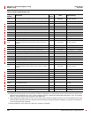
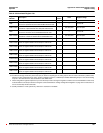
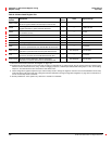
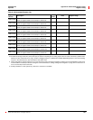
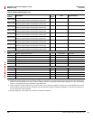
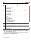
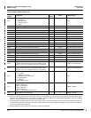
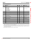
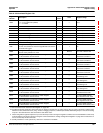
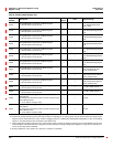
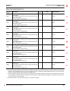
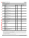
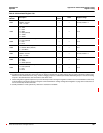
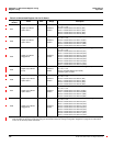
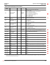
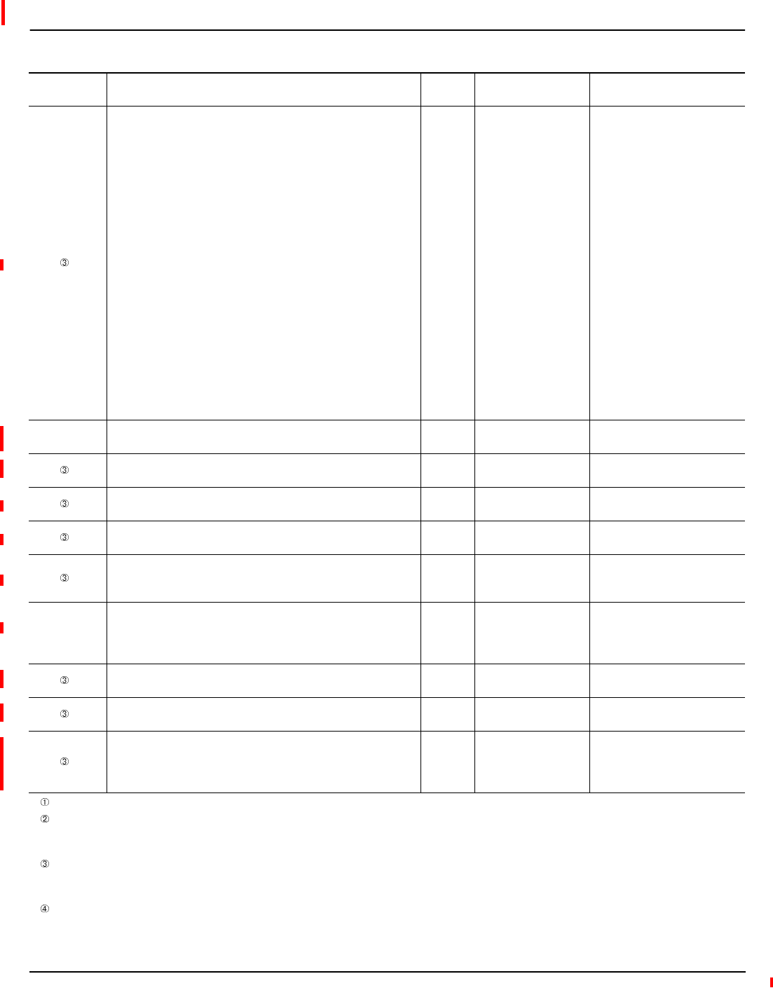
Table A–3:Abbreviated Register List
Register
Number
Description
Scale
Factor
Units Register Range
See “How Power Factor is Stored in the Register” on page 128.
The alternate storage method for power factor (PF) is useful for outputting PF on analog outputs. The PF value is stored as a positive value
between 0 and 2, centered around 1 (unity). A value of 0 lagging maps to0; -0.999 maps to 0.999;0.999 leadingmaps to 1.001; and 0 leading
maps to 2. The alternate PF is also stored with a scale factor 0.001.
These configuration registers require that you enter the setup mode to change the register’s contents. Issue command 9020 to enter setup
mode and 9021 to exit setup mode. See “Using the Command Interface to Change Configuration Registers” on page 187 for instructions on
howtousethesetup-modecommands.
Quantity available for 4-wire system only. Value set to -32,768 if not available.