


63230-300-212 Appendix A—Abbreviated Register Listing
April 2001 Register Listing
143
© 2001 Schneider Electric All Rights Reserved
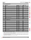
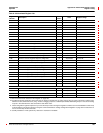
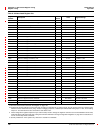
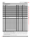
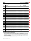
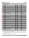
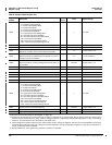
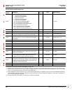
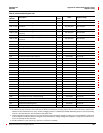
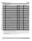
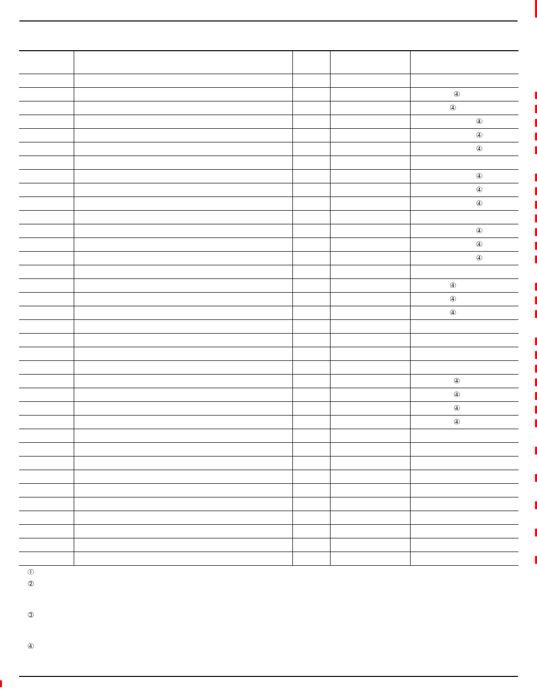
1649 Maximum Voltage Fundamental Coincident Angle, C-N/C-A — 0.1 ° 0to3,599
1650 Maximum Voltage Fundamental RMS Magnitude, N-G E Volts/Scale 0 to 32,767
1651 Maximum Voltage Fund. Coincident Angle, N-G — 0.1 ° 0to3,599
1655 Maximum Fundamental Real Power, Phase A F kW/Scale -32,767 to 32,767
1656 Maximum Fundamental Real Power, Phase B F kW/Scale -32,767 to 32,767
1657 Maximum Fundamental Real Power, Phase C F kW/Scale -32,767 to 32,767
1658 Maximum Fundamental Real Power, Total F kW/Scale -32,767 to 32,767
1659 Maximum Fundamental Reactive Power, Phase A F kVA/Scale -32,767 to 32,767
1660 Maximum Fundamental Reactive Power, Phase B F kVA/Scale -32,767 to 32,767
1661 Maximum Fundamental Reactive Power, Phase C F kVA/Scale -32,767 to 32,767
1662 Maximum Fundamental Reactive Power, Total F kVA/Scale -32,767 to 32,767
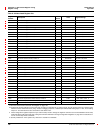
1664 Maximum Distortion Power, Phase A F kW/Scale -32,767 to 32,767
1665 Maximum Distortion Power, Phase B F kW/Scale -32,767 to 32,767
1666 Maximum Distortion Power, Phase C F kW/Scale -32,767 to 32,767
1667 Maximum Distortion Power, Total F kW/Scale -32,767 to 32,767
1668 Maximum Distortion Factor, Phase A F 0.10 0 to 1,000
1669 Maximum Distortion Factor, Phase B F 0.10 0 to 1,000
1670 Maximum Distortion Factor, Phase C F 0.10 0 to 1,000
1671 Maximum Distortion Factor, Total F 0.10 0 to 1,000
1674 Maximum Harmonic Current, Phase A A Amps/Scale 0 to 32,767
1675 Maximum Harmonic Current, Phase B A Amps/Scale 0 to 32,767
1676 Maximum Harmonic Current, Phase C A Amps/Scale 0 to 32,767
1677 Maximum Harmonic Current, Neutral B Amps/Scale 0 to 32,767
1678 Maximum Harmonic Voltage, A-N D Volts/Scale 0 to 32,767
1679 Maximum Harmonic Voltage, B-N D Volts/Scale 0 to 32,767
1680 Maximum Harmonic Voltage, C-N D Volts/Scale 0 to 32,767
1681 Maximum Total Demand Distortion — 0.01 0to10,000
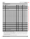
1684 Maximum Current, Positive Sequence, Magnitude A Amps/Scale 0 to 32,767
1685 Maximum Current, Positive Sequence, Angle — 0.1 0 to 3,599
1686 Maximum Current, Negative Sequence, Magnitude A Amps/Scale 0 to 32,767
1687 Maximum Current, Negative Sequence, Angle — 0.1 0 to 3,599
1688 Maximum Current, Zero Sequence, Magnitude A Amps/Scale 0 to 32,767
1689 Maximum Current, Zero Sequence, Angle — 0.1 0 to 3,599
1690 Maximum Voltage, Positive Sequence, Magnitude D Volts/Scale 0 to 32,767
1691 Maximum Voltage, Positive Sequence, Angle — 0.1 0 to 3,599
1692 Maximum Voltage, Negative Sequence, Magnitude D Volts/Scale 0 to 32,767
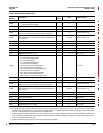
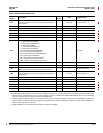
Table A–3:Abbreviated Register List
Register
Number
Description
Scale
Factor
Units Register Range
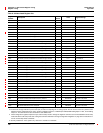
See “How Power Factor is Stored in the Register” on page 128.
The alternate storage method for power factor (PF) is useful for outputting PF on analog outputs. The PF value is stored as a positive value
between 0 and 2, centered around 1 (unity). A value of 0 lagging maps to 0; -0.999 maps to 0.999;0.999 leading maps to 1.001; and 0 leading
maps to 2. The alternate PF is also stored with a scale factor 0.001.
These configuration registers require that you enter the setup mode to change the register’s contents. Issue command 9020 to enter setup
mode and 9021 to exit setup mode. See “Using the Command Interface to Change Configuration Registers” on page 187 for instructions on
how to use the setup-mode commands.
Quantity available for 4-wire system only. Value set to -32,768 if not available.