


Appendix B—Using the Command Interface 63230-300-212
Overview of the Command Interface April 2001
© 2001 Schneider Electric All Rights Reserved
182
The circuit monitor provides a command interface, which you can use to
issue commands that perform various operations such as controlling relays.
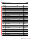
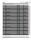
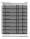
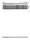
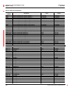
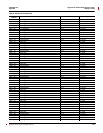
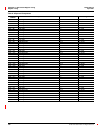
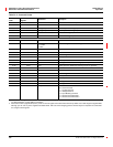
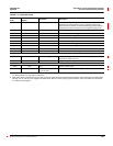
Ta bl e B– 2 on page 183 lists the available commands. The command
interface is located in memory at registers 8000–8149. Table B– 1 lists the
definitions for the registers.
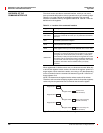
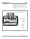
When registers 8017–8019 are set to zero, no values are returned. When any
or all of these registers contain a value, the value in the register “points” to a
target register, which contains the status, error code, or I/O data (depending
on the command) when the command is executed. Figure B–1 shows how
these registers work.
NOTE: You determine the register location where results will be written.
Therefore, take care when assigning register values in the pointer registers;
values may be corrupted when two commands use the same register.
Figure B–1: Command Interface Pointer Registers
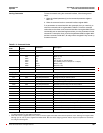
Table B– 1: Location of the command interface
Register Description
8000 This is the register where you write the commands.
8001–8015
These are the registers where you write the parameters for a
command. Commands can have up to 15 parameters associated
with them.
8017
Status pointer to the user area. The status of the last command
processed is placed in this register.
8018
Results pointer to the user area. When an error occurs, the error
code is placed in this register.
8019
I/O data pointer to the user area. Use this register to point to data
buffer registers where you can send additional data or return data.
8020–8149
These registers are for you (the user) to write information.
Depending on which pointer places the information in the register,
the register can contain status (from pointer 8017), results (from
pointer 8018), or data (from pointer 8019). The registers will contain
information such as whether the function is enabled or disabled, set
to fill and hold, start and stop times, logging intervals, and so forth.
By default, return data will start at 8020 unless you specify
otherwise.
OVERVIEW OF THE
COMMAND INTERFACE
8020
1
(status of the
last command)
Register 8017
Register 8020
8021
51
(error code caused by
the last command)
Register 8018
Register 8021
8022
0
(data returned by the
last command)
Register 8019
Register 8022