


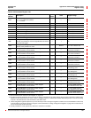
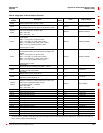
63230-300-212 Appendix A—Abbreviated Register Listing
April 2001 Register Listing
169
© 2001 Schneider Electric All Rights Reserved
Base + 10
Demand Interval Sync
System Assignments
—
0x0000 to
0x003F
Bitmap indicting Demand System(s) to which input is assigned.
(Default = 0x003F)
Bit 00 = Power Demand
Bit 01 = Current Demand
Bit 02 = Voltage Demand
Bit 03 = Input Metering Demand
Bit 04 = Generic Demand 1
Bit 05 = Generic Demand 2
Only one Demand Sync Pulse per Demand System is allowed. If
the user attemptsto configure more than one input for each system,
the lowest IO Point Number will take precedence. The
corresponding bits of the other points will be set to 0.
Base + 11
Digital Input Options —
0x0000 to
0x0001
Bitmap of digital Input Options. (Default = 0)
Bit 00 = Debounce time (0 = 5msec, 1 = 50msec)
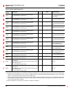
Base + 14
Metering Pulse
Channel Assignments
—
0x0000 to
0x03FF
Bitmap indicting metering pulse channel(s) to which input is
assigned. (Default = 0)
Bit 00 = Channel 1
Bit 01 = Channel 2
Bit 02 = Channel 3
Bit 03 = Channel 4
Bit 04 = Channel 5
Bit 05 = Channel 6
Bit 06 = Channel 7
Bit 07 = Channel 8
Bit 08 = Channel 9
Bit 09 = Channel 10
Base + 15
Metering Pulse
Weight, Demand
1.0 1- 32,767
Pulse weight associated with the change of state of the input. Used
for demand metering. (Default = 1)
Base + 16
Metering Pulse Scale
Factor, Demand
1.0 -3to3
Pulse weight scale factor (power of 10) to apply to metering pulse
weight. Used for demand metering. (Default = 0)
Base + 17
Metering Pulse
Weight, Consumption
1.0 1- 32,767
Pulse weight associated with the change of state of the input. Used
for consumption metering. (Default = 1)
Base + 18
Metering Pulse Scale
Factor, Consumption
1.0 -3to3
Pulse weight scale factor (power of 10) to apply to metering pulse
weight. Used for consumption metering. (Default = 0)
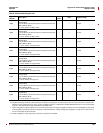
Base + 22
IO Point Diagnostic
Bitmap
—
0x0000 to
0xFFFF
IO Point Diagnostic Bitmap:
0 = OK, 1 = Error
Bit00=IOPointdiagnosticsummary
Bit 01 = Configuration invalid to default value used
Base + 25
Digital Input On/Off
Status
— 0 to 1 digital input Off/On status: 0 = Off, 1 = On
Base + 26 Count —
0to
99,999,999
Number of times input has transitioned from Off to On
Base + 28 On Time Seconds
0to
99,999,999
Duration that digital input has been On
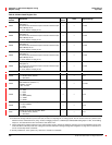
Digital Output Template
Table A–4:Abbreviated Register List for I/O Status
Register
Number
Name Units Range Description
These configuration registers require that you enter the setup mode to change the register’s contents. Issue command 9020 to enter setup
mode and 9021 to exit setup mode. See “Using the Command Interface to Change Configuration Registers” on page 187 for instructions
on how to use the setup-mode commands.