


Appendix A—Abbreviated Register Listing 63230-300-212
Register Listing April 2001
© 2001 Schneider Electric All Rights Reserved
148
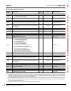
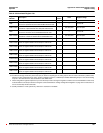
1900
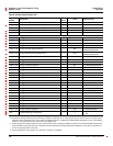
Demand Calculation Mode, Generic Group 2
0 = Thermal Demand (default)
1 = Timed Interval Sliding Block
2=TimedIntervalBlock
4 = Timed Interval Rolling Block
8 = Input Synchronized Block
16 = Input Synchronized Rolling Block
32 = Command Synchronized Block
64 = Command Synchronized Rolling Block
128 = Clock Synchronized Block
256 = Clock Synchronized Rolling Block
512 = Slave to Power Demand Interval
1024 = Slave to Incremental Energy Interval
——0to1024
1901
Demand Interval, Generic Group 2 — Minutes 1 to 60, Default = 15
1902
Demand Subinterval, Generic Group 2 — Minutes 1 to 60, Default = 1
1903
Demand Sensitivity, Generic Group 2
Adjusts the sensitivity of the thermal demand calculation.
— 1% 1to99,Default=90
1905
Short Demand Interval, Generic Group 2
Sets the interval for a running average demand calculation of
short duration.
— Seconds 0 to 60, Default = 15
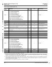
1906 Time Elapsed in Interval, Generic Group 2 — Seconds 0 to 3,600
1907 Time Elapsed in Subinterval, Generic Group 2 — Seconds 0 to 3,600
1908 Interval Count, Generic Group 2 — 1.0 0 to 32,767
1909 Subinterval Count, Generic Group 2 — 1.0 0 to 60
1910 to 1913 Min/Max Reset Date/Time, Generic Group 2 — See Template See Template
1914 Min/Max Reset Count, Generic Group 2 — 1.0 0 to 32,767
1920
Demand Forgiveness Duration
Duration of time after a power outage, during which power
demand is not calculated
— Seconds 0 to 3600
1921
Demand Forgiveness Outage Definition
Duration of time that metered voltage must be lost to be
considered a power outage for demand forgiveness
— Seconds 0 to 3600
1923
ClockSyncTimeofDay
Time of day, in minutes from midnight, to which the demand
interval is to be synchronized. Applies to demand intervals
configured as Clock Synchronized.
— Minutes 0 to 1440
1924 Power Factor Average Over Last Power Demand Interval — 0.001 1,000 -100 to 100
1925 to 1928 Cumulative Demand Reset Date/Time — See Template See Template
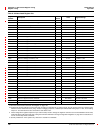
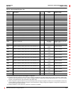
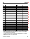
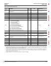
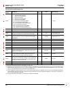
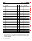
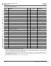
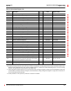
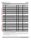
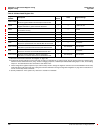
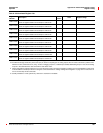
Table A–3:Abbreviated Register List
Register
Number
Description
Scale
Factor
Units Register Range
See “How Power Factor is Stored in the Register” on page 128.
The alternate storage method for power factor (PF) is useful for outputting PF on analog outputs. The PF value is stored as a positive value
between 0 and 2, centered around 1 (unity). A value of 0 lagging maps to0; -0.999 maps to 0.999;0.999 leadingmaps to 1.001; and 0 leading
maps to 2. The alternate PF is also stored with a scale factor 0.001.
These configuration registers require that you enter the setup mode to change the register’s contents. Issue command 9020 to enter setup
mode and 9021 to exit setup mode. See “Using the Command Interface to Change Configuration Registers” on page 187 for instructions on
howtousethesetup-modecommands.
Quantity available for 4-wire system only. Value set to -32,768 if not available.