


63230-300-212 Chapter 10—Maintenance and Troubleshooting
April 2001 Troubleshooting
125
© 2001 /Schneider Electric All Rights Reserved
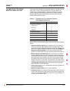
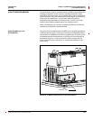
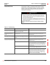
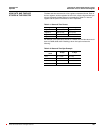
The information in Table 10–1 describes potential problems and their
possible causes. It also describes checks you can perform or possible
solutions for each. After referring to this table, if you cannot resolve the
problem, contact the your local Square D/Schneider Electric sales
representative for assistance.
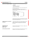
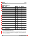
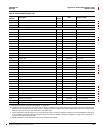
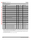
Table 10–1: Troubleshooting
Potential Problem Possible Cause Possible Solution
The red maintenance
LED is
illuminated on the circuit monitor.
When the red maintenance LED is illuminated, it
indicates a potential hardware or firmware
problem in the circuit monitor.
Contact your local sales representative for assistance.
The green control power LED is
not illuminated on the circuit
monitor.
The circuit monitor is not receiving the
necessary power.
Verify that the circuit monitor line (L) and neutral (N)
terminals (terminals 25 and 27) are receiving the
necessary power.
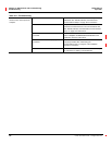
The display is blank after applying
control power to the circuit monitor.
The display is not receiving the necessary
power or communications signal from the circuit
monitor.
Verify that the display cable is properly inserted into the
connectors on the display and the circuit monitor.
The data being displayed is
inaccurate or not what you expect.
Circuit monitor is grounded incorrectly. Verify that the circuit monitor is grounded as described in
“Grounding the Circuit Monitor” on page 54 of the
installation manual.
Incorrect setup values. Check that the correct values have been entered for circuit
monitor setup parameters (CT and PT ratings, System
Type, Nominal Frequency, and so on). See “Setting Up the
Metering Functions of the Circuit Monitor” on page 16 for
setup instructions.
Incorrect voltage inputs. Check circuit monitor voltage input terminals (9, 10, 11,12)
to verify that adequate voltage is present.
Circuit monitor is wired improperly. Check that all CTs and PTs are connected correctly
(proper polarity is observed) and that they are energized.
Check shorting terminals. See “Wiring CTs, PTs, and
Control Power to the Circuit Monitor” on page 38 of the
installation manual for wiring diagrams. Initiate a wiring
check from the circuit monitor display.
TROUBLESHOOTING
HAZARD OF ELECTRIC SHOCK, BURN, OR EXPLOSION
• Beware of potential hazards, wear personal protective equipment,
carefully inspect the work area for tools and objects that may have
been left inside the equipment.
• Use caution while removing or installing panels so that they do not
extend into the energized bus; avoid handling the panels, which could
cause personal injury.
Failure to follow this instruction will result in death or serious
injury.
DANGER