


63230-300-212 Chapter 5—Input/Output Capabilities
April 2001 Analog Outputs
81
© 2001 Schneider Electric All Rights Reserved
This section describes the circuit monitor’s analog output capabilities. For
technical specifications and instructions on installing the I/O Extender or
analog output modules, refer to the instruction bulletin that ships with the I/O
(see Table 1–2 on page 3 for a list of these publications).
To set up analog outputs, you must first define it from the display. From the
main menu, select Setup > I/O. Select the appropriate analog output option.
For example, if you are using the IOX0404 option of the I/O Extender, select
IOX0404. For detailed instructions, see “SettingUpI/Os” on page 23
in Chapter 3—Operation.Thenusing
SMS, you must define the following
values for each analog output:
• Name—A 16-character label used to identify the output. Default names
are assigned, but can be customized
• Output register—The circuit monitor register assigned to the analog
output.
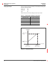
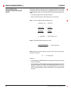
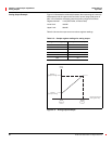
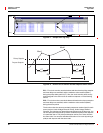
• Lower Limit—The value equivalent to the minimum output current. When
the register value is below the lower limit, the circuit monitor outputs the
minimum output current.
• Upper Limit—The value equivalent to the maximum output current. When
the register value is above the upper limit, the circuit monitor outputs the
maximum output current.
For instructions on setting up an analog output in
SMS,seetheSMS online
help on device set up of the circuit monitor.
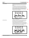
ANALOG OUTPUTS
HAZARD OF EQUIPMENT DAMAGE
Each analog output represents an individual 2-wire current loop;
therefore, use an isolated receiver for
each
individual analog output
on the I/O Extender (IOX).
Failure to observe this instruction can result in equipment damage.
CAUTION