


Appendix A—Abbreviated Register Listing 63230-300-212
Register Listing April 2001
© 2001 Schneider Electric All Rights Reserved
170
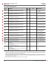
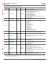
Base
IO Point Type — 200to299
IO Point Type to digital Output
First digit (2) indicates point is digital output.
Second digit indicates module type
0 = Generic digital output
1 = DO120AC Pluggable Module
2 = DO200DC Pluggable Module
3 = DO240AC Pluggable Module
4 = DO60DC Pluggable Module Third digit indicates output type
1 = solid state relay
2 = electromechanical relay
Base + 1
IO Point Label
Alpha-
Numeric
— 16-character label
Base + 9
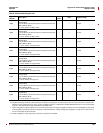
Mode — 0to11
digital Output Operating Mode
0 = Normal (default)
1 = Latched
2=Timed
3 = Absolute kWh pulse
4 = Absolute kVARh pulse
5=kVAhpulse
6=kWhInpulse
7=kVARhInpulse
8=kWhoutpulse
9=kVARhoutpulse
10 = Register-based pulse (future)
11 = End of power demand interval
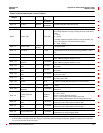
Base + 10
On Time For Timed
Mode
Seconds 1 to 32,767
The time for the output to remain energized when the output is in
timed mode or end of power demand interval. (Default = 1)
Base + 11
Pulse Weight
KWH/
Pulse
kVarH/
Pulse
kVAH/
Pulse in
100ths
1to32,767
Specifies the kWh, kVARh and kVAh per pulse for output when in
these modes. (Default = 1)
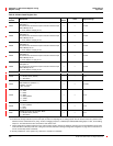
Base + 12
Internal/External
Control
— 0to1
Indicates active output state.
0 = Internal Control
1 = External Control (default)
Base + 13
Normal/Override
Control
— 0to1
Indicates active output state.
0 = Normal Control (default)
1 = Override Control
Base + 22
IO Point Diagnostic
Bitmap
—
0x0000 to
0x000F
IO Point Diagnostic Bitmap:
0=OK,1=Error
Bit00=IOPointdiagnosticsummary
Bit 01 = Configuration invalid to default value used
Bit 02 = digital output energy pulse to time between transitions
exceeds 30 seconds
Bit 03 = digital output energy pulse to time between transitions
limited to 20 milliseconds
Remaining bits not used.
Base + 25
Digital Output On/Off
Status
— 0 to 1 digital output Off/On status: 0 = Off, 1 = On
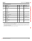
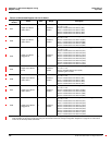
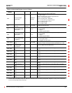
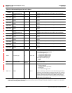
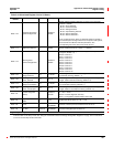
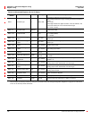
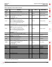
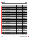
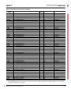
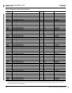
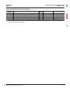
Table A–4:Abbreviated Register List for I/O Status
Register
Number
Name Units Range Description
These configuration registers require that you enter the setup mode to change the register’s contents. Issue command 9020 to enter setup
mode and 9021 to exit setup mode. See “Using the Command Interface to Change Configuration Registers” on page 187 for instructions
on how to use the setup-mode commands.