


Appendix A—Abbreviated Register Listing 63230-300-212
Register Listing April 2001
© 2001 Schneider Electric All Rights Reserved
132
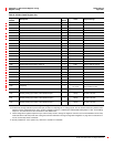
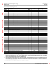
1144 Reactive Power, Phase A F kVAr/Scale -32,767 to 32,767
1145 Reactive Power, Phase B F kVAr/Scale -32,767 to 32,767
1146 Reactive Power, Phase C F kVAr/Scale -32,767 to 32,767
1147 Reactive Power, Total F kVAr/Scale -32,767 to 32,767
1148 Apparent Power, Phase A F kVA/Scale -32,767 to 32,767
1149 Apparent Power, Phase B F kVA /Scale -32,767 to 32,767
1150 Apparent Power, Phase C F kVA /Scale -32,767 to 32,767
1151 Apparent Power, Total F kVA /Scale -32,767 to 32,767
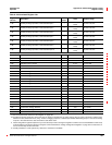
1160 True Power Factor, Phase A — 0.001 -100 to 1,000 to 100
1161 True Power Factor, Phase B — 0.001 -100 to 1,000 to 100
1162 True Power Factor, Phase C — 0.001 -100 to 1,000 to 100
1163 True Power Factor, Total — 0.001 -100 to 1,000 to 100
1164 Alternate True Power Factor, Phase A — 0.001 0 to 2,000
1165 Alternate True Power Factor, Phase B — 0.001 0 to 2,000
1166 Alternate True Power Factor, Phase C — 0.001 0 to 2,000
1167 Alternate True Power Factor, Total — 0.001 0 to 2,000
1168 Displacement Power Factor, Phase A — 0.001 -100 to 1,000 to 100
1169 Displacement Power Factor, Phase B — 0.001 -100 to 1,000 to 100
1170 Displacement Power Factor, Phase C — 0.001 -100 to 1,000 to 100
1171 Displacement Power Factor, Total — 0.001 -100 to 1,000 to 100
1172 Alternate Displacement Power Factor, Phase A — 0.001 0 to 2,000
1173 Alternate Displacement Power Factor, Phase B — 0.001 0 to 2,000
1174 Alternate Displacement Power Factor, Phase C — 0.001 0 to 2,000
1175 Alternate Displacement Power Factor, Total — 0.001 0 to 2,000
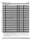
1180 Frequency —
0.01 Hertz
0.1 Hertz
(50/60) 2,300 to 6,700
(400) 3,500 to 4,500
1181 Temperature — 0.1 °C -1,000to1,000
1190 Auxiliary Analog Input Value, User-Selected Input 1 —
Refer to Analog Input
Setup
-32,767 to 32,767
1191 Auxiliary Analog Input Value, User-Selected Input 2 —
Refer to Analog Input
Setup
-32,767 to 32,767
1192 Auxiliary Analog Input Value, User-Selected Input 3 —
Refer to Analog Input
Setup
-32,767 to 32,767
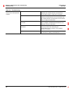
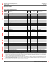
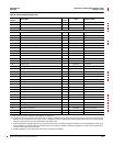
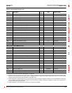
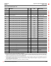
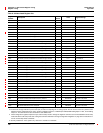
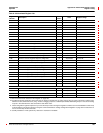
Table A–3:Abbreviated Register List
Register
Number
Description
Scale
Factor
Units Register Range
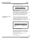
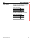
See “How Power Factor is Stored in the Register” on page 128.
The alternate storage method for power factor (PF) is useful for outputting PF on analog outputs. The PF value is stored as a positive value
between 0 and 2, centered around 1 (unity). A value of 0 lagging maps to0; -0.999 maps to 0.999;0.999 leadingmaps to 1.001; and 0 leading
maps to 2. The alternate PF is also stored with a scale factor 0.001.
These configuration registers require that you enter the setup mode to change the register’s contents. Issue command 9020 to enter setup
mode and 9021 to exit setup mode. See “Using the Command Interface to Change Configuration Registers” on page 187 for instructions on
howtousethesetup-modecommands.
Quantity available for 4-wire system only. Value set to -32,768 if not available.