


Chapter 3—Operation 63230-300-212
Configuring the Circuit Monitor Using The Setup Menu April 2001
© 2001 Schneider Electric All Rights Reserved
22
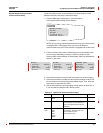
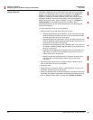
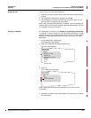
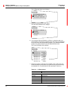
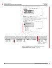
NOTE: If you are setting up or editing a digital alarm, fields related to
pickup and dropout are not applicable and will not be displayed.
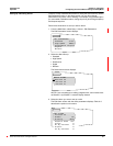
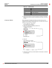
4. Use the arrow buttons to scroll to the menu option you want to change,
then edit the alarm options.
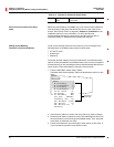
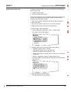
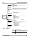
5. When you are finished with all changes, press the menu button until
“Save Changes? No” flashes on the display. Select Yes with the arrow
button, then press the enter button to save the changes.
NOTE: An asterisk next to the alarm in the alarm list indicates that the
alarm is enabled.
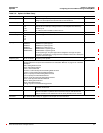
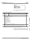
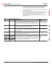
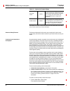
Table 3–5: Options for Editing an Alarm
Option Available Values Selection Description Default
Lbl Alphanumeric
Label—name of the alarm assigned to this position. Press the down arrow button
to scroll through the alphabet. The lower case letters are presented first, then
uppercase, then numbers and symbols. Press the enter button to select a letter
and move to the next character field. To move to the next option, press the menu
button.
Name of the alarm
assigned to this position.
Enable
Ye s
No
Select
Y
to make the alarm available for use by the circuit monitor. On
preconfigured alarms, the alarm may already be enabled.
Select
N
to makes the alarm function unavailable to the circuit monitor.
Depends on individual
alarm.
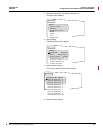
Priority
None
Low
Med
High
Low
is the lowest priority alarm.
High
is the highest priority alarm and also places
the active alarm in the list of high priority alarms. To view this list from the Main
Menu, select Alarms > High Priority Alarms. For more information, see “Viewing
Alarms” on page 41.
Depends on individual
alarm.
Setpoint Mode
Abs
Rel
Selecting Abs indicates that the pickup and dropout setpoints are absolute values.
Rel indicates that the pickup and dropout setpoints are a percentage of a running
average, the relative value, of the test value.
Pickup 1–32,767
When you enter a delay time, the number is multiples of time. For example, for
standard speed the time is 2 for 2 seconds, 3 for 3 seconds, etc. For high speed
alarms, 1 indicates a 100 ms delay, 2 indicates a 200 ms delay, and so forth. For
disturbance the time unit is 1 cycle. See “Setpoint-Driven Alarms” on page 85 for
an explanation of pickup and dropout setpoints.
Depends on individual
alarm.
PU Dly
Seconds
Pickup Delay
1–32,767
Dropout 1–32,767
DO Dly
Seconds
Dropout Delay
1–32,767