


Appendix A—Abbreviated Register Listing 63230-300-212
Register Listing April 2001
© 2001 Schneider Electric All Rights Reserved
166
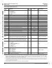
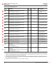
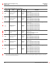
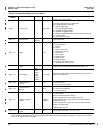
Table A–4:Abbreviated Register List for I/O Status
Register
Number
Name Units Range Description
4001
Digital Input Status
Option Slot A
—
0x0000 to
0xFFFF
Bitmap of On/Off status for the digital inputs in Option Slot A:
0 = Off, 1 = On
Bit 00 = On/Off Status of IO Point 3 (A01)
Bit 01 = On/Off Status of IO Point 4 (A02)
Bit 02 = On/Off Status of IO Point 5 (A03)
Bit 03 = On/Off Status of IO Point 6 (A04)
4002
Digital Input Status
Option Slot B
—
0x0000 to
0xFFFF
Bitmap of On/Off status for the digital inputs in Option Slot B:
0 = Off, 1 = On
Bit 00 = On/Off Status of IO Point 19 (B01)
Bit 01 = On/Off Status of IO Point 20 (B02)
Bit 02 = On/Off Status of IO Point 21 (B03)
Bit 03 = On/Off Status of IO Point 22 (B04)
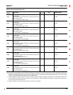
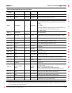
4003
Digital Input Status
Pluggable IO
—
0x0000 to
0x00FF
Bitmap of On/Off status for the digital inputs in Pluggable IO:
0 = Off, 1 = On
Bit 00 = On/Off Status of IO Point 35 (C01)
Bit 01 = On/Off Status of IO Point 36 (C02)
Bit 02 = On/Off Status of IO Point 37 (C03)
Bit 03 = On/Off Status of IO Point 38 (C04)
Bit 04 = On/Off Status of IO Point 39 (C05)
Bit 05 = On/Off Status of IO Point 40 (C06)
Bit 06 = On/Off Status of IO Point 41 (C07)
Bit 07 = On/Off Status of IO Point 42 (C08)
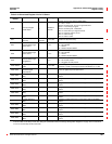
4005
Digital Output Status
(KYZ)
—
0x0000 to
0x0001
Bitmap of On/Off status for the standard digital output:
0 = Off, 1 = On
Bit 00 = Standard digital output (KYZ)
Remaining bits not used.
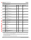
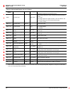
4006
Digital Output Status
Option Slot A
—
0x0000 to
0xFFFF
Bitmap of On/Off status for the digital outputs in Option Slot A:
0 = Off, 1 = On
Bit 00 = On/Off Status of IO Point 3 (A01)
Bit 01 = On/Off Status of IO Point 4 (A02)
Bit 02 = On/Off Status of IO Point 5 (A03)
Bit 03 = On/Off Status of IO Point 6 (A04)
4007
Digital Output Status
Option Slot B
—
0x0000 to
0xFFFF
Bitmap of On/Off status for the digital outputs in Option Slot B:
0 = Off, 1 = On
Bit 00 = On/Off Status of IO Point 19 (B01)
Bit 01 = On/Off Status of IO Point 20 (B02)
Bit 02 = On/Off Status of IO Point 21 (B03)
Bit 03 = On/Off Status of IO Point 22 (B04)
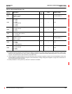
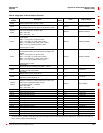
4008
Digital Output Status
Pluggable IO
—
0x0000 to
0x00FF
Bitmap of On/Off status for the digital outputs in Pluggable IO:
0 = Off, 1 = On
Bit 00 = On/Off Status of IO Point 35 (C01)
Bit 01 = On/Off Status of IO Point 36 (C02)
Bit 02 = On/Off Status of IO Point 37 (C03)
Bit 03 = On/Off Status of IO Point 38 (C04)
Bit 04 = On/Off Status of IO Point 39 (C05)
Bit 05 = On/Off Status of IO Point 40 (C06)
Bit 06 = On/Off Status of IO Point 41 (C07)
Bit 07 = On/Off Status of IO Point 42 (C08)
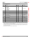
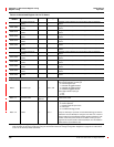
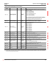
These configuration registers require that you enter the setup mode to change the register’s contents. Issue command 9020 to enter setup
mode and 9021 to exit setup mode. See “Using the Command Interface to Change Configuration Registers” on page 187 for instructions
on how to use the setup-mode commands.