


63230-300-212 Chapter 6—Alarms
April 2001 Alarm Conditions and Alarm Numbers
97
© 2001 Schneider Electric All Rights Reserved
054 Leading Power Factor
The leading power factor alarm will occur when the test register value becomes more leading than
the pickup setpoint (such as closer to 0.010) and remains more leading long enough to satisfy the
pickup delay period. When the value becomes equal to or less leading than the dropout setpoint,
that is 1.000, and remains less leading for the dropout delay period, the alarm will dropout. Both
the pickup setpoint and the dropout setpoint must be positive values representing leading power
factor. Enter setpoints as integer values representing power factor in thousandths. For example, to
define a dropout setpoint of 0.5, enter 500. Delays are in seconds.
055 Lagging Power Factor
The lagging power factor alarm will occur when the test register value becomes more lagging than
the pickup setpoint (such as closer to –0.010) and remains more lagging long enough to satisfy the
pickup delay period. When the value becomes equal to or less lagging than the dropout setpoint,
that is 1.000, and remains less lagging for the dropout delay period, the alarm will dropout. Both
the pickup setpoint and the dropout setpoint must be positive values representing lagging power
factor. Enter setpoints as integer values representing power factor in thousandths. For example, to
define a dropout setpoint of –0.5, enter 500. Delays are in seconds.
High Speed
010 Over Value Alarm
If the test register value exceeds the setpoint long enough to satisfy the pickup delay period, the
alarm condition will be true. When the value in the test register falls below the dropout setpoint long
enough to satisfy the dropout delay period, the alarm will dropout. Pickup and dropout setpoints
are positive, delays are in hundreds of milliseconds.
011 Over Power Alarm
If the absolute value in the test register exceeds the setpoint long enough to satisfy the pickup delay
period, the alarm condition will be true. When the value in the test register falls below the dropout
setpoint long enough to satisfy the dropout delay period, thealarm will dropout. Pickup and dropout
setpoints are positive, delays are in hundreds of milliseconds.
012 Over Reverse Power Alarm
If the absolute value in the test register exceeds the setpoint long enough to satisfy the pickup delay
period, the alarm condition will be true. When the value in the test register falls below the dropout
setpoint long enough to satisfy the dropout delay period, the alarm will dropout. This alarm will only
hold true for reverse power conditions. Positive power values will not cause the alarm to occur.
Pickup and dropout setpoints are positive, delays are in hundreds of milliseconds.
020 Under Value Alarm
If the test register value is below the setpoint long enough to satisfy the pickup delay period, the
alarm condition will be true. When the value in the test register rises above the dropout setpoint
long enough to satisfy the dropout delay period, the alarm will dropout. Pickup and dropout
setpoints are positive, delays are in hundreds of milliseconds.
021 Under Power Alarm
If the absolute value inthe test register is below the setpoint long enough to satisfy the pickup delay
period, the alarm condition will be true. When the value in the test register rises above the dropout
setpoint long enough to satisfy the dropout delay period, thealarm will dropout. Pickup and dropout
setpoints are positive, delays are in hundreds of milliseconds.
051 Phase Reversal
The phase reversal alarm will occur when ever the phase voltage waveform rotation differs from the
default phase rotation. The ABC phase rotation is assumed to be normal. If a CBA normal phase
rotation is normal, the user should reprogram the circuit monitor’s phase rotation ABC to CBA
phase rotation. The pickup and dropout setpoints and delays for phase reversal do no apply.
052 Phase Loss, Voltage
The phase loss voltage alarm will occur when any one or two phase voltages (but not all) fall to the
pickup value and remain at or below the pickup value long enough to satisfy the specified pickup
delay. When all of the phases remain at or above the dropout value for the dropout delay period, or
when all of the phases drop below the specified phase loss pickup value, the alarm will dropout.
Pickup and dropout setpoints are positive, delays are in seconds.
053 Phase Loss, Current
The phase loss current alarm will occur when any one or two phase currents (but not all) fall to the
pickup value and remain at or below the pickup value long enough to satisfy the specified pickup
delay. When all of the phases remain at or above the dropout value for the dropout delay period, or
when all of the phases drop below the specified phase loss pickup value, the alarm will dropout.
Pickup and dropout setpoints are positive, delays are in hundreds of milliseconds.
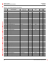
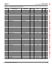
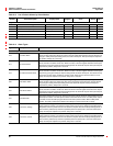
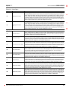
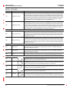
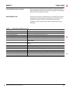
Table 6–4: Alarm Types
Type Description Operation