


63230-300-212 Appendix A—Abbreviated Register Listing
April 2001 Register Listing
157
© 2001 Schneider Electric All Rights Reserved
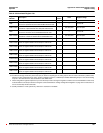
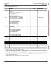
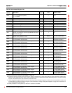
3050
Self-Test Results
0=Normal
1 = Error
Bit 00 = Is set to "1" if any failure occurs
Bit 01 = RTC failure
Bit02=MCFUart#1failure
Bit03=MCFUart#2failure
Bit 04 = PLD Uart failure
Bit 05 = Metering Collection overrun failure
Bit 06 = Metering Process 0.1 overrun failure
Bit 07 = Metering Process 1.0 overrun failure
Bit 08 = Disk-on-Chip failure
Bit 09 = Display failure
Bit 10 = CV Module failure
Bit11=AuxPlugEEPROMfailure
Bit 12 = Flash Memory failure
Bit 13 = Dram Memory failure
Bit 14 = Simtek Memory failure
Bit 15 = RTC Memory failure
——0x0000 to 0xFFFF
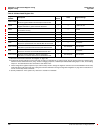
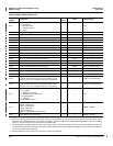
3051
Self Test Results
0=Normal
1 = Error
Bit 00 = Aux IO failure
Bit 01 = Option Slot A module failure
Bit 02 = Option Slot B module failure
Bit 03 = IOX module failure
Bit 08 = OS Create failure
Bit09=OSQueueoverrunfailure
Bit 13 = Systems shut down due to continuous reset
Bit 14 = Unit in Download, Condition A
Bit 15 = Unit in Download, Condition B
——0x0000 to 0xFFFF
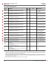
3053 Installed Log Memory — Clusters 0to65,535
3054 Free Log Memory — Clusters 0to65,535
3093 Present Month — Months 1to12
3094 Present Day — Days 1to31
3095 Present Year — Years 2000to2043
3096 Present Hour — Hours 0 to 23
3097 Present Minute — Minutes 0 to 59
3098 Present Second — Seconds 0 to 59
3099
Day of Week
1 = Sunday, 2 = Monday, etc.
——1to7
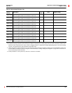
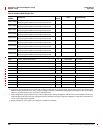
Current and Voltage Module Configuration
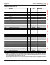
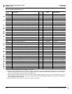
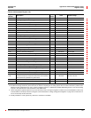
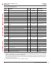
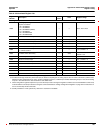
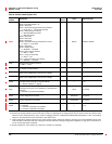
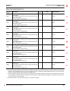
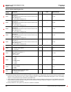
Table A–3:Abbreviated Register List
Register
Number
Description
Scale
Factor
Units Register Range
See “How Power Factor is Stored in the Register” on page 128.
The alternate storage method for power factor (PF) is useful for outputting PF on analog outputs. The PF value is stored as a positive value
between 0 and 2, centered around 1 (unity). A value of 0 lagging maps to 0; -0.999 maps to 0.999;0.999 leading maps to 1.001; and 0 leading
maps to 2. The alternate PF is also stored with a scale factor 0.001.
These configuration registers require that you enter the setup mode to change the register’s contents. Issue command 9020 to enter setup
mode and 9021 to exit setup mode. See “Using the Command Interface to Change Configuration Registers” on page 187 for instructions on
how to use the setup-mode commands.
Quantity available for 4-wire system only. Value set to -32,768 if not available.