


Appendix A—Abbreviated Register Listing 63230-300-212
Register Listing April 2001
© 2001 Schneider Electric All Rights Reserved
158
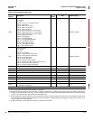
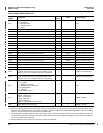
3100
Current-Voltage Module Product ID Number
0=Notpresent
1 = Standard CVM
2 = Overrange CVM
3=CVMT
——0to3
3137 CVMT Operating System Firmware Revision —
3138
CT Ratio, Phase A Correction Factor — 0.00001 -20,000 to 20,000, Default = 0
3139
CT Ratio, Phase B Correction Factor — 0.00001 -20,000 to 20,000, Default = 0
3140
CT Ratio, Phase C Correction Factor — 0.00001 -20,000 to 20,000,Default = 0
3141
CT Ratio, Neutral Correction Factor — 0.00001 -20,000 to 20,000,Default = 0
3142
PT Ratio, Phase A Correction Factor — 0.00001 -20,000 to 20,000, Default = 0
3143
PT Ratio, Phase B Correction Factor — 0.00001 -20,000 to 20,000, Default = 0
3144
PT Ratio, Phase C Correction Factor — 0.00001 -20,000 to 20,000, Default = 0
3145
Neutral-Ground Correction Factor — 0.00001 -20,000 to 20,000, Default = 0
3154
Phase A Current Field Calibration Coefficient — 0.00001 -20,000 to 20,000, Default = 0
3155
Phase B Current Field Calibration Coefficient — 0.00001 -20,000 to 20,000, Default = 0
3156
Phase C Current Field Calibration Coefficient — 0.00001 -20,000 to 20,000, Default = 0
3157
Neutral Current Field Calibration Coefficient — 0.00001 -20,000 to 20,000, Default = 0
3158
Phase A Voltage Field Calibration Coefficient — 0.00001 -20,000 to 20,000, Default = 0
3159
Phase B Voltage Field Calibration Coefficient — 0.00001 -20,000 to 20,000, Default = 0
3160
Phase C Voltage Field Calibration Coefficient — 0.00001 -20,000 to 20,000, Default = 0
3161
Neutral-Ground Voltage Field Calibration Coefficient — 0.00001 -20,000 to 20,000, Default = 0
3170
CTPhaseShiftCorrection@1amp
CT phase shift correction, for user instrumentation, in the
range of -10º to +10º. A negative shifts in the lag direction.
——-1,000 to 1,000, Default = 0
3171
CTPhaseShiftCorrection@5amps
CT phase shift correction, for user instrumentation, in the
range of -10º to +10º. A negative shifts in the lag direction.
——-1,000 to 1,000, Default = 0
3174
CVMT Mode
0=Undefined
1 = Waiting for download
2 = Waiting for meter initialization
3 = Normal operation
4 = Calibration
5 = Firmware download
——0to5
3175
CVMT Diagnostics
Bit 00 = Summary bit
Bit01=InvalidMode
Bit 02 = Read error
Bit03=Writeerror
Bit04=InvalidCVMTfirmwareversion
——0x0000 to 0xFFFF
3176 CVMT Reset Firmware Revision ——0x0000 to 0xFFFF
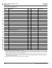
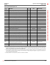
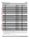
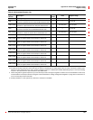
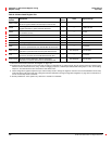
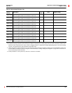
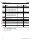
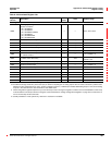
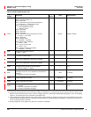
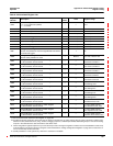
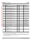
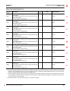
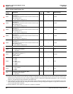
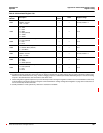
Table A–3:Abbreviated Register List
Register
Number
Description
Scale
Factor
Units Register Range
See “How Power Factor is Stored in the Register” on page 128.
The alternate storage method for power factor (PF) is useful for outputting PF on analog outputs. The PF value is stored as a positive value
between 0 and 2, centered around 1 (unity). A value of 0 lagging maps to0; -0.999 maps to 0.999;0.999 leadingmaps to 1.001; and 0 leading
maps to 2. The alternate PF is also stored with a scale factor 0.001.
These configuration registers require that you enter the setup mode to change the register’s contents. Issue command 9020 to enter setup
mode and 9021 to exit setup mode. See “Using the Command Interface to Change Configuration Registers” on page 187 for instructions on
howtousethesetup-modecommands.
Quantity available for 4-wire system only. Value set to -32,768 if not available.