


63230-300-212 Chapter 3—Operation
April 2001 Configuring the Circuit Monitor Using The Setup Menu
17
© 2001 Schneider Electric All Rights Reserved
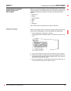
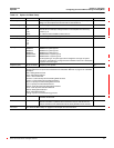
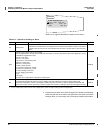
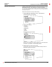
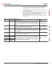
Table 3–3: Options for Meter Setup
Option Available Values Selection Description Default
CT Primary 1–32,767 Set the rating for the CT primary. The circuit monitor supports two primary CT
ratings: one for the phase CTs and the other for the neutral CT.
5
CT Secondary 1 or 5 Set the rating for the CT secondaries. 5
PT Pri Scale x1
x10
x100
No PT
Set the value to which the PT Primary is to be scaled if the PT Primary is larger
than 32,767. For example, setting the scale to x10 multiplies the PT Primary
number by 10.
For a direct-current installation, select “No PT.”
x1
PT Primary 1–32,767 Set the rating for the PT primary. 120
PT Secondary 100
110
115
120
Set the rating for the PT secondaries. 120
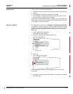
Sys Type 3Ø3W2CT
3Ø3W3CT
3Ø4W3CT
3Ø4W4CT
3Ø4W3CT2PT
3Ø4W4CT2PT
3Ø3W2CT is system type 30
3Ø3W3CT is system type 31
3Ø4W3CT is system type 40
3Ø4W4CT is system type 41
3Ø4W3CT2PT is system type 42
3Ø4W4CT2PT is system type 43
Set the system type. A system type code is assigned to each type of system
connection. See Table 5–2 on page 38 of the installation manual for a description
of system connection types.
3Ø4W3CT (40)
Frequency (Hz) 50, 60, or 400 Hz Frequency of the system. 60
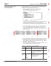
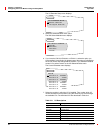
Pwr Dmd Meth Select the power demand calculation method. The circuit monitor supports several methods to calculate
average demand of real power. See “Demand Power Calculation Methods” on page 57 for a detailed
description.
Slide—Sliding Block Demand
Slave—Slave Block Demand
Therm—Thermal Demand
RComms—Command-Synchronized Rolling Block Demand
Comms—Command-Synchronized Block Demand
RInput—Input-Synchronized Rolling Block Demand
Input—Input-Synchronized Block Demand
RClock—Clock-Synchronized Rolling Block Demand
Clock—Clock-Synchronized Block Demand
RBlock—Rolling Block Demand
Block—Fixed Block Demand
IncEngy—Synch to Incremental Energy Interval
Slide
Pwr Dmd Int 1–60 Power demand interval—set the time in minutes in which the circuit monitor
calculates the demand.
15
Pwr Dmd Sub Interval 1–60 Power demand subinterval—period of time within the demand interval in which the
demand calculation is updated. Set the subinterval only for methods that will
accept a subinterval. The subinterval must be evenly divisible into the interval.
N/A
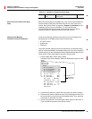
Advanced See “Advanced Meter Setup” on page 34 in this chapter for more information.