


LDW Load Word From Memory With a 5-Bit Unsigned Constant Offset or Register Offset
3-136 Instruction Set SPRU733
Load Word From Memory With a 5-Bit Unsigned Constant Offset or
Register Offset
LDW
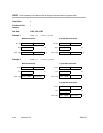
Syntax Register Offset
LDW (.unit) *+baseR[offsetR], dst
Unsigned Constant Offset
LDW (.unit) *+baseR[ucst5], dst
.unit = .D1 or .D2
Compatibility C62x, C64x, C67x, and C67x+ CPU
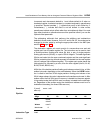
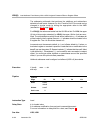
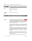
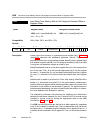
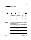
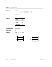
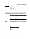
Opcode
31 29 28 27 23 22 18 17 13 12 9 8 7 6 4 3 2 1 0
creg z dst baseR offsetR/ucst5 mode 0 y 1 1 0 0 1 s p
3 1 5 5 5 4 1 1 1
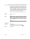
Description Loads a word from memory to a general-purpose register (dst). Table 3−11
(page 3-33) describes the addressing generator options. The memory
address is formed from a base address register (baseR) and an optional offset
that is either a register (offsetR) or a 5-bit unsigned constant (ucst5). If an offset
is not given, the assembler assigns an offset of zero.
offsetR and baseR must be in the same register file and on the same side as
the .D unit used. The y bit in the opcode determines the .D unit and register
file used: y = 0 selects the .D1 unit and baseR and offsetR from the A register
file, and y = 1 selects the .D2 unit and baseR and offsetR from the B register
file.
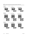
offsetR/ucst5 is scaled by a left-shift of 2 bits. After scaling, offsetR/ucst5 is
added to or subtracted from baseR. For the preincrement, predecrement,
positive offset, and negative offset address generator options, the result of the
calculation is the address to be accessed in memory. For postincrement or
postdecrement addressing, the value of baseR before the addition or subtrac-
tion is the address to be accessed in memory.
The addressing arithmetic that performs the additions and subtractions
defaults to linear mode. However, for A4−A7 and for B4−B7, the mode can be
changed to circular mode by writing the appropriate value to the AMR
(see section 2.7.3, page 2-10).
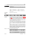
For LDW, the entire 32 bits fills dst. dst can be in either register file, regardless
of the .D unit or baseR or offsetR used. The s bit determines which file dst will
be loaded into: s = 0 indicates dst will be loaded in the A register file and s = 1
indicates dst will be loaded in the B register file. The r bit should be cleared to
0.