


Addressing Modes
3-31Instruction SetSPRU733
3.8.2 Circular Addressing Mode
The BK0 and BK1 fields in AMR specify the block sizes for circular addressing,
see section 2.7.3.
3.8.2.1 LD and ST Instructions
As with linear address arithmetic, offsetR/cst is shifted left by 3, 2, 1, or 0
according to the data size, and is then added to or subtracted from baseR to
produce the final address. Circular addressing modifies this slightly by only
allowing bits N through 0 of the result to be updated, leaving bits 31 through
N + 1 unchanged after address arithmetic. The resulting address is bounded
to 2
(N
+
1)
range, regardless of the size of the offsetR/cst.
The circular buffer size in AMR is not scaled; for example, a block-size of 8 is
8 bytes, not 8 times the data size (byte, halfword, word). So, to perform circular
addressing on an array of 8 words, a size of 32 should be specified, or N = 4.
Example 3−4 shows an LDW performed with register A4 in circular mode and
BK0 = 4, so the buffer size is 32 bytes, 16 halfwords, or 8 words. The value in
AMR for this example is 0004 0001h.
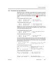
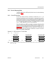
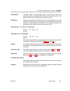
Example 3−4. LDW Instruction in Circular Mode
LDW .D1 *++A4[9],A1
Before LDW 1 cycle after LDW 5 cycles after LDW
A4
0000 0100h
A4 0000 0104h A4 0000 0104h
A1 XXXX XXXXh A1 XXXX XXXXh A1
1234 5678h
mem 104h 1234 5678h mem 104h 1234 5678h mem 104h 1234 5678h
Note: 9h words is 24h bytes. 24h bytes is 4 bytes beyond the 32-byte (20h) boundary 100h−11Fh; thus, it is wrapped around to
(124h − 20h = 104h).