


Pipeline Operation Overview
4-9PipelineSPRU733
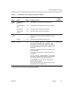
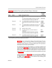
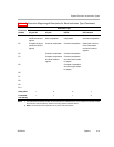
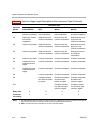
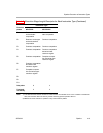
Table 4−1. Operations Occurring During Pipeline Phases (Continued)
Stage
Instruction
Type
Completed
During This PhaseSymbolPhase
Execute 5 E5 For load instructions, data is written into a register
file.
†
For INTDP and MPYSP2DP instructions, the upper
32 bits of the result are written to a register file.
†
Load INTDP
MPYSP2DP
Execute 6 E6 For ADDDP/SUBDP and MPYSPDP instructions, the
lower 32 bits of the result are written to a register
file.
†
ADDDP/
SUBDP,
MPYSPDP
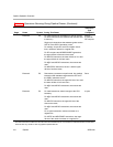
Execute 7 E7 For ADDDP/SUBDP and MPYSPDP instructions, the
upper 32 bits of the result are written to a register
file.
†
ADDDP/
SUBDP,
MPYSPDP
Execute 8 E8 Nothing is read or written.
Execute 9 E9 For MPYI instruction, the result is written to a
register file.
†
For MPYDP and MPYID instructions, the lower
32 bits of the result are written to a register file.
†
MPYI
MPYDP
MPYID
Execute 10 E10 For MPYDP and MPYID instructions, the upper
32 bits of the result are written to a register file.
MPYDP
MPYID
†
This assumes that the conditions for the instructions are evaluated as true. If the condition is evaluated as false, the instruction
does not write an y results or have any pipeline operation after E1.
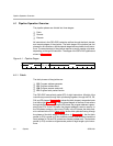
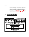
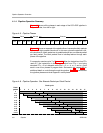
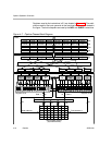
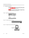
Figure 4−7 shows a functional block diagram of the pipeline stages. The pipe-
line operation is based on CPU cycles. A CPU cycle is the period during which
a particular execute packet is in a particular pipeline phase. CPU cycle bound-
aries always occur at clock cycle boundaries.
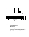
As code flows through the pipeline phases, it is processed by different parts
of the C67x DSP. Figure 4−7 shows a full pipeline with a fetch packet in every
phase of fetch. One execute packet of eight instructions is being dispatched
at the same time that a 7-instruction execute packet is in decode. The arrows
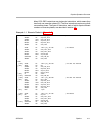
between DP and DC correspond to the functional units identified in the code
in Example 4−1.
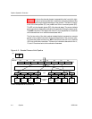
In the DC phase portion of Figure 4−7, one box is empty because a NOP was
the eighth instruction in the fetch packet in DC, and no functional unit is needed
for a NOP. Finally, Figure 4−7 shows six functional units processing code
during the same cycle of the pipeline.