


Pipeline Operation Overview
Pipeline4-6 SPRU733
4.1.4 Pipeline Operation Summary
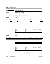
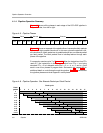
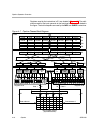
Figure 4−5 shows all the phases in each stage of the C67x DSP pipeline in
sequential order, from left to right.
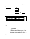
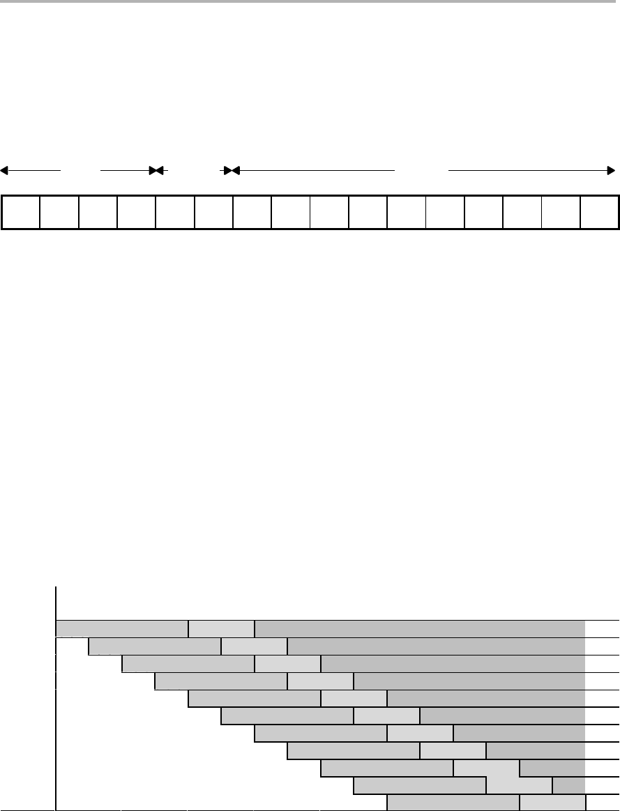
Figure 4−5. Pipeline Phases
Fetch Execute
Decode
PG PS PW PR DP DC E1 E2 E3 E4 E5 E6 E7 E8 E9 E10
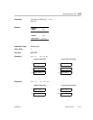
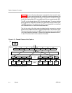
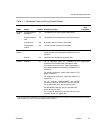
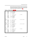
Figure 4−6 shows an example of the pipeline flow of consecutive fetch packets
that contain eight parallel instructions. In this case, where the pipeline is full,
all instructions in a fetch packet are in parallel and split into one execute packet
per fetch packet. The fetch packets flow in lockstep fashion through each
phase of the pipeline.
For example, examine cycle 7 in Figure 4−6. When the instructions from FPn
reach E1, the instructions in the execute packet from FPn +1 are being
decoded. FP n + 2 is in dispatch while FPs n + 3, n + 4, n + 5, and n + 6 are
each in one of four phases of program fetch. See section 4.4, page 4-56, for
additional detail on code flowing through the pipeline. Table 4−1 summarizes
the pipeline phases and what happens in each phase.
Figure 4−6. Pipeline Operation: One Execute Packet per Fetch Packet
Clock cycle
Fetch
packet
1
234567891011121314151617
n PG PS PW PR DP DC E1 E2 E3 E4 E5 E6 E7 E8 E9 E10
n+1 PG PS PW PR DP DC E1 E2 E3 E4 E5 E6 E7 E8 E9 E10
n+2 PG PS PW PR DP DC E1 E2 E3 E4 E5 E6 E7 E8 E9
n+3 PG PS PW PR DP DC E1 E2 E3 E4 E5 E6 E7 E8
n+4 PG PS PW PR DP DC E1 E2 E3 E4 E5 E6 E7
n+5 PG PS PW PR DP DC E1 E2 E3 E4 E5 E6
n+6 PG PS PW PR DP DC E1 E2 E3 E4 E5
n+7 PG PS PW PR DP DC E1 E2 E3 E4
n+8 PG PS PW PR DP DC E1 E2 E3
n+9 PG PS PW PR DP DC E1 E2
n+10 PG PS PW PR DP DC E1