


Instruction Operation and Execution Notations
Instruction Set3-2 SPRU733
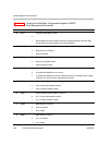
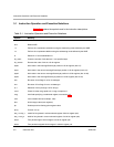
3.1 Instruction Operation and Execution Notations
Table 3−1 explains the symbols used in the instruction descriptions.
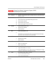
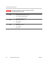
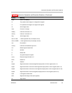
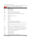
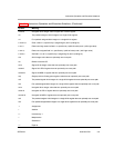
Table 3−1. Instruction Operation and Execution Notations
Symbol Meaning
abs(x) Absolute value of x
and Bitwise AND
−a Perform 2s-complement subtraction using the addressing mode defined by the AMR
+a Perform 2s-complement addition using the addressing mode defined by the AMR
b
i
Select bit i of source/destination b
bit_count Count the number of bits that are 1 in a specified byte
bit_reverse Reverse the order of bits in a 32-bit register
byte0 8-bit value in the least-significant byte position in 32-bit register (bits 0-7)
byte1 8-bit value in the next to least-significant byte position in 32-bit register (bits 8-15)
byte2 8-bit value in the next to most-significant byte position in 32-bit register (bits 16-23)
byte3 8-bit value in the most-significant byte position in 32-bit register (bits 24-31)
bv2 Bit vector of two flags for s2 or u2 data type
bv4 Bit vector of four flags for s4 or u4 data type
b
y..z
Selection of bits y through z of bit string b
cond Check for either creg equal to 0 or creg not equal to 0
creg 3-bit field specifying a conditional register, see section 3.6
cstn n-bit constant field (for example, cst5)
dint 64-bit integer value (two registers)
dp Double-precision floating-point register value
dp(x) Convert x to dp
dst_h or dst_o msb32 of dst (placed in odd-numbered register of 64-bit register pair)
dst_l or dst_e lsb32 of dst (placed in even-numbered register of a 64-bit register pair)
dws4 Four packed signed 16-bit integers in a 64-bit register pair
dwu4
Four packed unsigned 16-bit integers in a 64-bit register pair