


Interrupt Detection and Processing
Interrupts5-16 SPRU733
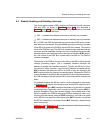
5.4 Interrupt Detection and Processing
When an interrupt occurs, it sets a flag in the interrupt flag register (IFR).
Depending on certain conditions, the interrupt may or may not be processed.
This section discusses the mechanics of setting the flag bit, the conditions for
processing an interrupt, and the order of operation for detecting and proces-
sing an interrupt. The similarities and differences between reset and nonreset
interrupts are also discussed.
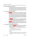
5.4.1 Setting the Nonreset Interrupt Flag
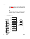
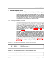
Figure 5−4 shows the processing of a nonreset interrupt (INTm). The flag
(IFm) for INTm in the IFR is set following the low-to-high transition of the INTm
signal on the CPU boundary. This transition is detected on a clock-cycle by
clock-cycle basis and is not affected by memory stalls that might extend a CPU
cycle. Once there is a low-to-high transition on an external interrupt pin
(cycle 1), it takes two clock cycles for the signal to reach the CPU boundary
(cycle 3). When the interrupt signal enters the CPU, it is has been detected
(cycle 4). Two clock cycles after detection, the interrupt’s corresponding flag
bit in the IFR is set (cycle 6).
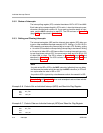
In Figure 5−4, IFm is set during CPU cycle 6. You could attempt to clear IFm
by using an MVC instruction to write a 1 to bit m of the ICR in execute packet
n + 3 (during CPU cycle 4). However, in this case, the automated write by the
interrupt detection logic takes precedence and IFm remains set.
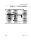
Figure 5−4 assumes INTm is the highest-priority pending interrupt and is
enabled by GIE and NMIE, as necessary. If it is not the highest-priority pending
interrupt, IFm remains set until either you clear it by writing a 1 to bit m of the
ICR or the processing of INTm occurs.
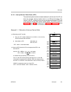
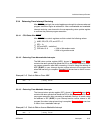
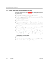
5.4.2 Conditions for Processing a Nonreset Interrupt
In clock cycle 4 of Figure 5−4, a nonreset interrupt in need of processing is
detected. For this interrupt to be processed, the following conditions must be
valid on the same clock cycle and are evaluated every clock cycle:
IFm is set during CPU cycle 6. (This determination is made in CPU cycle 4
by the interrupt logic.)
There is not a higher priority IFm bit set in the IFR.
The corresponding bit in the IER is set (IEm = 1).
GIE = 1
NMIE = 1
The five previous execute packets (n through n + 4) do not contain a
branch (even if the branch is not taken) and are not in the delay slots of
a branch.