


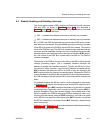

Individual Interrupt Control
Interrupts5-14 SPRU733
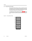
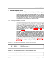
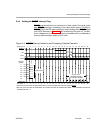
5.3.2 Status of Interrupts
The interrupt flag register (IFR) contains the status of INT4−INT15 and NMI.
Each interrupt’s corresponding bit in IFR is set to 1 when that interrupt occurs;
otherwise, the bits have a value of 0. If you want to check the status of inter-
rupts, use the MVC instruction to read IFR. The IFR is shown in Figure 2−8
(page 2-18) and described in Table 2−10.
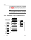
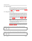
5.3.3 Setting and Clearing Interrupts
The interrupt set register (ISR) and the interrupt clear register (ICR) allow you
to set or clear maskable interrupts manually in IFR. Writing a 1 to IS4−IS15 in
ISR causes the corresponding interrupt flag to be set in IFR. Similarly, writing
a 1 to a bit in ICR causes the corresponding interrupt flag to be cleared. Writing
a 0 to any bit of either ISR or ICR has no effect. Incoming interrupts have prior-
ity and override any write to ICR. You cannot set or clear any bit in ISR or ICR
to affect NMI or reset. The ISR is shown in Figure 2−10 (page 2-20) and
described in Table 2−11. The ICR is shown in Figure 2−6 (page 2-16) and
described in Table 2−8.
Note:
Any write to the ISR or ICR (by the MVC instruction) effectively has one delay
slot because the results cannot be read (by the MVC instruction) in IFR until
two cycles after the write to ISR or ICR.
Any write to ICR is ignored by a simultaneous write to the same bit in ISR.
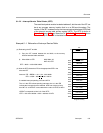
Example 5−6 and Example 5−7 show code examples to set and clear individu-
al interrupts, respectively.
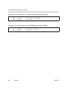
Example 5−6. Code to Set an Individual Interrupt (INT6) and Read the Flag Register
MVK 40h,B3
MVC B3,ISR
NOP
MVC IFR,B4
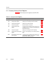
Example 5−7. Code to Clear an Individual Interrupt (INT6) and Read the Flag Register
MVK 40h,B3
MVC B3,ICR
NOP
MVC IFR,B4