


Globally Enabling and Disabling Interrupts
5-11InterruptsSPRU733
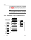
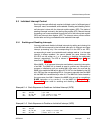
5.2 Globally Enabling and Disabling Interrupts
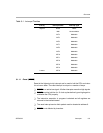
The control status register (CSR) contains two fields that control interrupts:
GIE and PGIE, as shown in Figure 2−4 (page 2-13) and described in
Table 2−7 (page 2-14). The global interrupt enable (GIE) allows you to enable
or disable all maskable interrupts:
GIE = 1 enables the maskable interrupts so that they are processed.
GIE = 0 disables the maskable interrupts so that they are not processed.
Bit 1 of CSR is the PGIE bit and holds the previous value of GIE when a mask-
able interrupt is processed. During maskable interrupt processing, the value
of the GIE bit is copied to the PGIE bit, and the GIE bit is cleared. The previous
value of the PGIE bit is lost. The GIE bit is cleared during a maskable interrupt
to prevent another maskable interrupt from occurring before the device state
has been saved. Upon returning from an interrupt, by way of the B IRP instruc-
tion, the content of the PGIE bit is copied back to the GIE bit. The PGIE bit
remains unchanged.
The purpose of the PGIE bit is to record the value of the GIE bit at the time the
interrupt processing begins. This is necessary because interrupts are
detected in parallel with instruction execution. Typically, the GIE bit is 1 when
an interrupt is taken. However, if an interrupt is detected in parallel with an
MVC instruction that clears the GIE bit, the GIE bit may be cleared by the
MVC instruction after the interrupt processing begins. Because the PGIE bit
records the state of the GIE bit after all instructions have completed execution,
the PGIE bit captures the fact that the GIE bit was cleared as the interrupt was
taken.
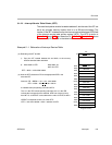
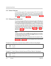
For example, suppose the GIE bit is set to 1 as the sequence of code shown
in Example 5−2 is entered. An interrupt occurs, and the CPU detects it just as
the CPU is executing the MVC instruction that writes a 0 to the GIE bit. Interrupt
processing begins. Meanwhile, the 0 is written to the GIE bit as the MVC in-
struction completes. During the interrupt dispatch, this updated value of the
GIE bit is copied to the PGIE bit, leaving the PGIE bit cleared to 0. Later, upon
returning from the interrupt (using the B IRP instruction), the PGIE bit is copied
to the GIE bit. As a result, the code following the MVC instruction recognizes
the GIE bit is cleared to 0, as directed by the MVC instruction, despite having
taken the interrupt.
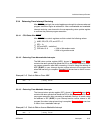
Example 5−2 and Example 5−3 show code examples for disabling and enabling
maskable interrupts globally, respectively.