


Performance Considerations
4-57PipelineSPRU733
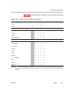
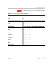
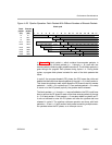
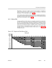
Figure 4−28. Pipeline Operation: Fetch Packets With Different Numbers of Execute Packets
Clock cycle
Fetch
packet
(FP)
Execute
packet
(EP)
1
2 3 4 5 6 7 8 9 10 11 12 13 14 15 16 17
nk
PG PS PW PR DP DC E1 E2 E3 E4 E5 E6 E7 E8 E9 E10
n k+1 DP DC E1 E2 E3 E4 E5 E6 E7 E8 E9 E10
n k+2 DP DC E1 E2 E3 E4 E5 E6 E7 E8 E9
n+1 k+3 PG PS PW PR DP DC E1 E2 E3 E4 E5 E6 E7 E8
n+2 k+4 PG PS PW Pipeline PR DP DC E1 E2 E3 E4 E5 E6 E7
n+3 k+5 PG PS stall PW PR DP DC E1 E2 E3 E4 E5 E6
n+4 k+6 PG PS PW PR DP DC E1 E2 E3 E4 E5
n+5 k+7 PG PS PW PR DP DC E1 E2 E3 E4
n+6 k+8 PG PS PW PR DP DC E1 E2 E3
In Figure 4−28, fetch packet n, which contains three execute packets, is
shown followed by six fetch packets (n + 1 through n + 6), each with one
execute packet (containing eight parallel instructions). The first fetch packet (n)
goes through the program fetch phases during cycles 1−4. During these
cycles, a program fetch phase is started for each of the fetch packets that
follow.
In cycle 5, the program dispatch (DP) phase, the CPU scans the p-bits and
detects that there are three execute packets (k through k + 2) in fetch packet n.
This forces the pipeline to stall, which allows the DP phase to start for execute
packets k + 1 and k + 2 in cycles 6 and 7. Once execute packet k + 2 is ready
to move on to the DC phase (cycle 8), the pipeline stall is released.
The fetch packets n + 1 through n + 4 were all stalled so the CPU could have
time to perform the DP phase for each of the three execute packets (k through
k + 2) in fetch packet n. Fetch packet n + 5 was also stalled in cycles 6 and 7:
it was not allowed to enter the PG phase until after the pipeline stall was
released in cycle 8. The pipeline continues operation as shown with fetch
packets n + 5 and n + 6 until another fetch packet containing multiple execu-
tion packets enters the DP phase, or an interrupt occurs.