


The way each instruction is described Example
3-35 Instruction SetSPRU733
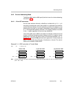
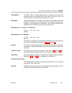
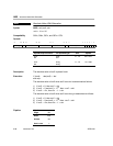
The way each instruction is described.
Example
Syntax EXAMPLE (.unit) src, dst
.unit = .L1, .L2, .S1, .S2, .D1, .D2
src and dst indicate source and destination, respectively. The (.unit) dictates
which functional unit the instruction is mapped to (.L1, .L2, .S1, .S2, .M1, .M2,
.D1, or .D2).
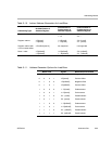
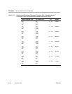
A table is provided for each instruction that gives the opcode map fields, units
the instruction is mapped to, types of operands, and the opcode.
The opcode shows the various fields that make up each instruction. These
fields are described in Table 3−2 on page 3-7.
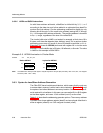
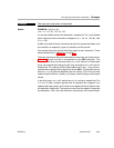
There are instructions that can be executed on more than one functional unit.
Table 3−12 shows how this is documented for the ADD instruction. This
instruction has three opcode map fields: src1, src2, and dst. In the seventh
group, the operands have the types cst5, long, and long for src1, src2, and dst,
respectively. The ordering of these fields implies cst5 + long ³ long, where +
represents the operation being performed by the ADD. This operation can be
done on .L1 or .L2 (both are specified in the unit column). The s in front of each
operand signifies that src1 (scst5), src2 (slong), and dst (slong) are all signed
values.
In the third group, src1, src2, and dst are int, int, and long, respectively. The
u in front of each operand signifies that all operands are unsigned. Any
operand that begins with x can be read from a register file that is different from
the destination register file. The operand comes from the register file opposite
the destination, if the x bit in the instruction is set (shown in the opcode map).