


Conditional Operations
3-19Instruction SetSPRU733
3.6 Conditional Operations
Most instructions can be conditional. The condition is controlled by a 3-bit
opcode field (creg) that specifies the condition register tested, and a 1-bit field
(z) that specifies a test for zero or nonzero. The four MSBs of every opcode
are creg and z. The specified condition register is tested at the beginning of
the E1 pipeline stage for all instructions. For more information on the pipeline,
see Chapter 4. If z = 1, the test is for equality with zero; if z = 0, the test is for
nonzero. The case of creg = 0 and z = 0 is treated as always true to allow
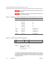
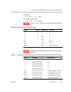
instructions to be executed unconditionally. The creg field is encoded in the
instruction opcode as shown in Table 3−9.
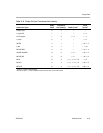
Table 3−9. Registers That Can Be Tested by Conditional Operations
Specified
C diti l
creg z
Conditional
Register
Bit
31 30 29 28
Unconditional 0 0 0 0
Reserved
†
000 1
B0 001 z
B1 010 z
B2 011 z
A1 100 z
A2 101 z
Reserved
1 1 x
‡
x
‡
†
This value is reserved for software breakpoints that are used for emulation purposes.
‡
x can be any value.
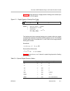
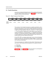
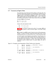
Conditional instructions are represented in code by using square brackets, [ ],
surrounding the condition register name. The following execute packet
contains two ADD instructions in parallel. The first ADD is conditional on B0
being nonzero. The second ADD is conditional on B0 being zero. The charac-
ter ! indicates the inverse of the condition.
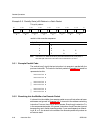
[B0] ADD .L1 A1,A2,A3
|| [!B0] ADD .L2 B1,B2,B3
The above instructions are mutually exclusive, only one will execute. If they
are scheduled in parallel, mutually exclusive instructions are constrained as
described in section 3.7. If mutually exclusive instructions share any resources
as described in section 3.7, they cannot be scheduled in parallel (put in the
same execute packet), even though only one will execute.